Effect of Chenodeoxycholic Acid as Dye Co-Adsorbent and ZnO Blocking Layer in Improving The Performance of Rose Bengal Dye Based Dye Sensitized Solar Cells

DOI: https://doi.org/10.21203/rs.3.rs-554033/v1

Abstract

Effective suppression of dye aggregation on the photoanode surface of dye sensitized solar cell plays a key role in improving the solar cell efficiency. Chenodeoxycholic acid (CDCA) is a very popular anti dye aggregation material used in Dye sensitized solar cells. However, the selection of an improper concentration of CDCA may lead to decreased solar cell efficiency by lowering the open circuit voltage and short circuit current as a consequence of reduced dye loading. The influence of chenodeoxycholic acid (CDCA) as a dye co-adsorbent on the performance of DSSCs fabricated using Rose Bengal dye was studied in this paper. The concentration of the CDCA solution was varied to identify the optimum value for the best device performance. Aside from this, the effect of a very thin and compact ZnO blocking layer was also investigated to reduce the recombination. With photovoltaic parameters such as short circuit current density (Jsc) = 1.98 mA/cm2, open circuit voltage (Voc) = 0.58 V, and fill factor (FF) = 0.43, the traditional cell displayed an overall conversion efficiency of 0.50 %, while the power conversion efficiency was found to be increased to 0.97 % ( Jsc = 2.80 mA/cm2, Voc= 0.64, FF = 0.58 ) when CDCA was added at optimised concentration of 8 mM. Reduced dye aggregation and increased electron injection in the presence of CDCA may be accounted for the DSSC's remarkable improvement in efficiency. Moreover, the combined effect of 8 mM CDCA and the compact ZnO blocking layer dramatically enhanced the efficiency further to 1.23 % (Jsc = 3.09 mA/cm2, Voc= 0.66, FF = 60 ). Electrochemical impedance spectroscopic (EIS) analysis revealed that the addition of CDCA as a co-adsorbent in the dye solution and addition of ZnO blocking layer resulted in significantly improved electron lifetime and reduced electron recombination yielding improved Jsc, Voc and η.

1. Introduction

Ever growing global energy requirement and depleting level of fossil fuels have accelerated the demand for efficient power generation from solar photovoltaic (PV) cells in recent years(Bach 1998; Meadows et al. 1972; Hosenuzzaman et al. 2015). The environmental impact of the use of fossil fuels is another major concern (Barbir et al. 1990). The current production of photovoltaic (PV) modules is dominated by crystalline silicon modules based on bulk wafers. However, the use of toxic materials and the high production cost of these solar cells have motivated the researchers to find new kinds of less expensive and non silicon-based solar cells to harvest solar energy efficiently (Goetzberger et al. 2003; Alharbi et al. 2011; Lee and Ebong 2017; Yamamoto et al. 2001).

Dye-sensitized solar cells (DSSCs) are a non-conventional photovoltaic technology that has attracted significant attention because of their high conversion efficiencies and low cost. O’Regan. B. & Grätzel reported high efficiency cells using nanoporous titanium dioxide (TiO2) semiconductor electrodes, ruthenium (Ru) metal complex dyes, and iodine electrolyte solutions in the journal of Nature in 1991 (O’Regan and Grätzel 1991). Since then, many studies have been actively carried out on DSSCs and revealed their performance comparable to amorphous silicon thin films (Chiba et al. 2006; Grätzel 2005). These DSSCs have the advantages of low cost, lightweight and easy fabrication, but issues include durability and further improvement of their properties. To respond to these issues, many attempts have been made, such as solidifying electrolytes and improving materials and structures, but there have been no great breakthroughs yet (Chung et al. 2012; Cai et al. 2011).

A dye-sensitized solar cell consists of two conducting glass electrodes in a sandwich arrangement. Each layer has a specific role in the cell. The transparent glass electrodes allow the light to pass through the cell. The titanium dioxide serves as a holding place for the dye and participates in electron transfer. The dye molecules collect light and produce excited electrons which cause a current in the cell. The iodide electrolyte layer acts as a source for electron replacement. The bottom conductive layer is coated with platinum which plays the role of the counter electrode. A schematic structure of a liquid electrolyte DSSC and its working principle is shown in Fig. 1. When light passes through the conductive glass electrode, the dye molecules absorb the photons and the electrons in the dye go from the ground state (HOMO) to an empty excited state (LUMO). This is referred to as photoexcitation. The excited electrons jump to the conduction band of the semiconducting dioxide and diffuse across this layer reaching the conductive electrode. Then they travel through the outer circuit and reach the counter electrode. The dye molecules become oxidized after losing an electron to the semiconductor oxide material. The red-ox iodide electrolyte donates electrons to the oxidized dye molecules thereby regenerating them. When the originally lost electron reaches the counter electrode, it gives the electron back to the electrolyte (O’Regan and Grätzel 1991; Grätzel 2003).

The photovoltaic performance of a DSSC highly depends on all of its components and the fabrication methodology. Therefore, the optimization of every component is extremely crucial to achieve the best performance. Since its introduction into the science community in 1991, the nanocrystalline photoanode in dye-sensitized solar cells have predominantly been comprised of titanium (TiO2) nanoparticles as the semiconducting material (O’Regan and Grätzel 1991; Grätzel 2003; Shao et al. 2011). Many researchers became very interested in studying the dye-sensitized solar cell performance fabricated using alternative semiconducting nanomaterials (Tiwana et al. 2011; Biswas and Chatterjee 2020). Specifically, Zinc Oxide (ZnO) has been an ideal alternative to TiO2 because of having a similar conduction band edge that is appropriate for proper electron injection from the excited dyes; moreover, ZnO provides better electron transport due to its higher electronic mobility. Along with that, ZnO is also highly transparent, which allows greater light penetration (Zhang et al. 2009; Guillén et al. 2011; Quintana et al. 2007; Vittal and Ho 2017; Biswas et al. 2019).

In this study, ZnO nanoparticles were implemented to fabricate the photoanode of the DSSCs and rose bengal dye was utilized as a sensitizer. To obtain better efficiency, the dye molecules must bind tightly to the mesoporous ZnO photoanode surface with the assistance of their anchoring group to ensure proficient electron injection from the LUMO of dye molecule to the conduction band (CB) of ZnO.

To make the DSSCs cost-effective, it is very essential to identify efficient and inexpensive dyes in place of costly ruthenium complexes. In that aspect, rose bengal dye has emerged as a promising alternative candidate. However, dye aggregation on the ZnO surface affects the photoelectron injection and hence limits the overall device performance (Zhang and Cole 2017). The use of additives such as CDCA is a very useful and widely used strategy in lowering the self-aggregation of dye molecules by suppressing unfavourable dye-dye interactions and thereby enhances the photoconversion efficiency (Buene et al. 2020; Kumar et al. 2020; Ismail et al. 2018). However, the strong binding of CDCA molecules to the ZnO surface partially displaces dye molecules and consequently reduces photon harvesting. Therefore, to maximize the positive effect of the co-adsorbent, it is very crucial to carefully optimize the amount of CDCA (Li et al. 2011). Herein, we report the effect of CDCA as co-adsorbent in the performance of Rose Bengal (RB) dye based DSSCs. Different concentrations of CDCA were studied to identify the optimum one for achieving the best device performance.

On the other hand, the mesoporous nature of the ZnO film is very essential to tender high surface area offering more dye loading and thereby generating more photoelectrons. However, small pores present in the nanocrystalline ZnO layer of the photoanode may provide a path for the direct contact between the liquid electrolyte and the FTO substrate. This may allow the electrons of FTO to recombine with the I3 ion present in the electrolyte resulting in high recombination current and hence decreased cell performance (Yang et al. 2014; Yeoh and Chan 2019). Therefore, to inhibit the electron back transfer, a promising approach is to modify the FTO/electrolyte interface by adding a compact metal oxide blocking layer. A thin blocking layer (BL) of ZnO was deposited by a facile and cost-effective sol-gel spin coating process before depositing the mesoporous active ZnO layer. In this work, we reported the fabrication and characterization of DSSCs based on ZnO nanoparticle and Rose Bengal dye. The effect of CDCA concentration and the compact ZnO blocking layer in boosting the photovoltaic performance of the device was investigated in terms of photocurrent-voltage (J-V) characteristics and dark current measurement. In addition to that, electrochemical impedance spectroscopy (EIS) analysis was employed to investigate the charge transfer kinetics and electron back reaction of the fabricated cells.

2. Materials And Methods

2.1. Materials

ZnO nanopowder, Zinc acetate dehydrate (CH3COO)2Zn, 2H2O) and Monoethanolamine (MEA) were bought from Sigma Aldrich, India. ethylcellulose and terpineol were bought from TCI Chemicals, India. Transparent FTO coated glass (10 Ω/ square), the high-performance liquid electrolyte (Iodolyte AN50), chenodeoxycholic acid (CDCA) as a dye co-adsorbent and liquid platinum paint (Platisol T) to prepare the platinum-coated counter electrode were purchased from Solaronix, Switzerland. Meltonix 1170-25 (25µm) (Solaronix) was used as a spacer between the working and counter electrode to avoid short-circuiting. All the reagents utilized in the fabrication process were of analytical grades. So no further purification was required.

2.2. Preparation of conventional ZnO photoanode

To prepare the thin films of the photoanode materials, the FTO coated glass substrates were first cleaned with dilute HCl in an ultrasonic bath for 15 minutes and then thoroughly rinsed with deionized water to remove the HCL residues. The substrates were then cleaned with acetone and ethanol using an ultrasonic cleaning bath (Biswas and Chatterjee 2020; Biswas et al. 2019). The mesoporous ZnO photoelectrode of the DSSC was prepared by following the standard doctor blade method. The paste for doctor blading was prepared by mixing 0.5 g of ZnO nanopowder with α-terpineol as a solvent and 0.45 g of ethyl cellulose as a binder (Wong et al. 2012). The mixture was stirred continuously to obtain a smooth lump-free slurry. The ZnO paste was then coated on the conductive side of the cleaned FTO glass substrate and subsequently annealed at 400oC on a hot plate for 30 min to burn out the ethyl cellulose and other organic contents of the working electrode and to strengthening the bonding between the substrate and the ZnO film. In addition to that, the annealing procedure also helps to improve the surface quality of the thin film along with increasing the crystallinity of the sample (Elilarassi and Chandrasekaran 2010; Shivaraj et al. 2015; Al-Kahlout 2015; Pandey et al. 2017).

2.3. Preparation of photoanode with Compact ZnO layer

In order to improve the photovoltaic performance of the cells further by preventing the direct contact between FTO and liquid electrolyte, a thin and compact ZnO layer was deposited on FTO coated glass substrate by employing a simple sol-gel spin coating method prior to deposition of mesoporous active ZnO nanoparticle layer. The precursor solution was prepared by mixing Zinc acetate dehydrate (CH3COO)2Zn, 2H2O) in 50 ml isopropanol as solvent and monoethanolamine (MEA) was used as a stabilizer. The precursor solution concentration was maintained at 0.05 M. The mixture was vigorously stirred at 60° C by a magnetic stirrer for 1 hr. MEA was added dropwise under stirring, yielding a clear homogenous solution. The solution was left for 24 hr at room temperature for aging before it could be used for film deposition. The aged solution was then spin-coated on a cleaned FTO glass substrate with a programmable spin coater (Apex Instruments Co. Pvt. Ltd, Model SpinNXG-P1)at 3000 rpm for 30 s and annealed at 200° C for 20 minutes to form the ZnO blocking layer. Over this compact blocking layer, the mesoporous active layer was coated using the same doctor blade method and then annealed at 400° C as done earlier.

2.4. Assembling the devices

One set of ZnO photoanodes were sensitized by immersing them in a 0.5 mM ethanolic solution of pure Rose Bengal dye for 12 hours. Another set of photoanodes (both with and without ZnO blocking layer) were sensitized with the RB dye solution containing various concentrations ( 0 mM – 10 mM) of CDCA at room temperature for 12 hours. The working electrodes were then removed from the solution and rinsed thoroughly with deionized water and ethanol to get rid of any excess dye from the thin film surface and left for air drying at room temperature. The platinum catalyst precursor solution (Platisol-T) was spin-coated on the conducting side of the cleaned FTO glasses and heated at 450o C for 15 minutes on a hot plate to prepare the counter electrodes for the cells. The dye adsorbed working electrodes and platinum(Pt)-coated counter electrodes were assembled against the coated sides of each other in a sandwich manner using two binder clips with a Surlyn film (Meltonix 1170-25µm, Solaronix) gasket as a spacer in between them. The liquid electrolyte used in the fabrication process was poured inside the cell through fine holes pre-drilled on the counter electrodes. The red-ox concentration of the electrolyte was 50 mM. The active area of the cells for illumination was adjusted to 0.16 cm2.

2.5. Characterization and Measurements

PAN-analytical X'Pert PRO X-ray diffractometer (CuKα radiation, 30 mA, 40 kV, λ = 1.5406 Å) was used to determine the crystalline structure of ZnO nanoparticles. Scanning electron microscopy (JEOL) was used to examine the surface morphology of the prepared ZnO thin films. Absorbance spectrum measurement of the dye was carried out using a Perkin-Elmer Lambda-35 UV-VIS spectrophotometer. The current-voltage (J-V) characterization of the cells was measured under 100 mW/cm2 illumination using a Keithley 2400 digital source meter which was controlled by Keithley LabTracer computer software. The overall photoconversion efficiency of the solar cell was calculated using the formula

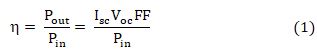
Where Pin, Voc, Isc and FF denote the incident photon power, open-circuit voltage, the short circuit current density and fill factor respectively. The fill factor was estimated using the following formula:

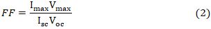
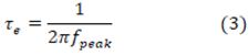
Where Imax and Vmax, respectively, represent values of current and voltage at the maximum output power point of the solar cell. The electrochemical impedance spectroscopy (EIS) of the cells was done in the frequency range of 0.1Hz to 190 kHz under open circuit conditions.

3. Results And Discussion

3.1. UV-VIS absorption spectral analysis of the dye

UV-VIS absorption spectrum of the Rose Bengal dye is shown in Fig. 3. The Rose Bengal dye absorbs a larger fraction of the solar spectrum in the visible region of 460–600 nm and it shows the highest optical absorption at 549 nm wavelength.

3.2. Structural and phase characterization ZnO compact layer

X-ray diffraction analysis was employed to figure out the crystal structure of the ZnO nanopowder used in making the photoanode of the DSSC. The X-ray diffraction pattern of the ZnO compact blocking layer, shown in Fig. 2, exhibits the hexagonal wurtzite crystal phase of ZnO and the peaks well match with the standard JCPDS card no. 36-1451. The diffraction peaks observed at 2θ values of 31.79°, 34.42°, 36.25°, 47.51°, 56.60°, 62.86°, 67.96°, and 69°corresponds to the reflection from the (100), (002), (101), (110), (103), (112), and (201) lattice planes respectively. Sharp and strong peaks indicate the highly crystalline nature of the material (Costantino et al. 1998; Oh et al. 2002).

3.3. Surface Morphology study and energy dispersive spectroscopy of the photoanodes

Scanning electron microscopic (SEM) analysis of the ZnO active layer and the compact blocking layer on the FTO substrate was carried out to study the surface morphology and the particle size of the sample. The SEM images of the ZnO active and blocking layers on the FTO substrate are depicted in Fig. 4. It can be seen from Fig. 4 (a) that the ZnO nanoparticles have a hexagonal structure. Figure 4(b) and (c) represent the SEM images of compact blocking layer at low and high magnifications respectively. The diameter of the spin-coated nanoparticles ranges from 150 to 180 nm. Further, the chemical composition and elemental percentage of the compact ZnO film are revealed by the EDS analysis which is shown in Fig. 4(d). Predominating peaks of Zn and O2 unveil that the synthesized blocking layer contains pure ZnO.

3.4. Photovoltaic characterization of the cells

The Current-Voltage (J-V) characteristic is a crucial measurement that reveals the value of the overall photovoltaic performance of a solar cell along with the key performance parameters like open circuit voltage and short circuit current density. Figure 5(a) depicts the J-V characteristics of the DSSCs based on different types of photoanodes used in this study and the obtained photovoltaic parameters for each of the cells are summarized in Table 1.

Table 1. Photovoltaic parameters of DSSCs fabricated with various ZnO photoanodes

Cell name

CDCA concentration

Jsc (mA/cm2)

Voc(V)

FF

Efficiency (η %)

RB1

0 mM

1.98

0.58

0.43

0.50

RB2

2 mM

2.08

0.61

0.58

0.74

RB3

4 mM

2.18

0.62

0.60

0.80

RB4

6 mM

2.36

0.63

0.58

0.87

RB5

8 mM

2.80

0.64

0.56

0.97

RB6

10 mM

2.63

0.64

0.54

0.90

RB7

8 mM + BL

3.09

0.66

0.60

1.23


3.4.1. Effect of CDCA

The conventionally prepared DSSC with ZnO nanoparticles and Rose Bengal dye displayed a short circuit current density (Jsc) of 1.98 mA/cm2, an open circuit voltage (Voc) of 0.58 V, and a fill factor (FF) of 0.43, resulting in a photoconversion efficiency(η) of 0.50 %. However, under the same working conditions, the device performance was found to be highly influenced when CDCA solution was incorporated into the dye solution at various concentrations. From Table 1, it can be noted that the value of Voc, as well as Jsc, increases with an increase in the concentration of CDCA. The best device performance was achieved for the optimized CDCA concentration of 8 mM when added with 0.5 mM RB dye solution. This improvement in the performance may be attributed to reduced dye aggregation along with uniform dye adsorption yielding better electron injection into the conduction band of ZnO.

3.4.2. Effect of compact ZnO blocking layer

To avoid the direct contact between the FTO and the liquid electrolyte through the pores present in the nanocrystalline ZnO film in a conventionally prepared DSSC, a thin and compact layer of ZnO was employed as shown in Fig. 6. From Table 1 it can be observed that the addition of a compact ZnO blocking layer in DSSC7 with 8 mM CDCA additive shows a remarkable enhancement in Jsc (3.09 mA/cm2) and Voc (0.66 V) and consequently the highest value of photoconversion efficiency η (1.23 %) was obtained among all the fabricated cells. Such type of performance enhancement may be accredited to the consolidated effect of improved dye loading due to the addition of CDCA with proper concentration and increased charge collection along with decreased electron recombination at the FTO/ZnO/electrolyte interface hindering the direct contact between FTO and electrolyte by the blocking layer.

3.4.3. Dark current measurement

To explore the effect of CDCA concentration and ZnO blocking layer in the process of electron back transfer, the J-V characteristics were also measured in the dark which is shown in Fig. 5(b). It is regarded as a qualitative method to assess the degree of electron back transfer in DSSCs. The dark current generation is known to be partly due to the presence of exposed FTO sites having direct contact with the liquid electrolyte and the pores left between the ZnO nanoparticles and the FTO surface (Yang et al. 2014; Yeoh and Chan 2019). These exposed FTO sites and the pores of ZnO nanoparticle film would allow the liquid electrolyte to penetrate through ZnO film and directly come in contact with bare FTO sites resulting in recombination losses as shown in the energy band diagram for conventional ZnO NP based DSSC in Fig. 7(a). It can be observed from Fig. 5(b) that the dark current has the highest value for conventionally prepared DSSC with bare FTO and decreases with an increase in CDCA concentration up to 8 mM. It can also be observed that for the cell (DSSC7) with compact ZnO BL and 8 mM CDCA solution as dye co-adsorbent, the dark current is reduced significantly for the same bias potential in comparison to all other cells. This demonstrates that the compact ZnO BL reduces the bare FTO site and thereby successfully suppresses the dark current by lowering the electron back transfer. It was also observed that the DSSC7 has the slowest rate of increase of dark current with an increase in bias voltage confirming excellent suppression of electron recombination and consequently reduced current loss.

The variations of different cell parameters with the concentration of CDCA solution for the fabricated DSSCs are depicted in Fig. 8. It can be observed that CDCA concentration highly influences the value of Jsc. ZnO BL improves the current further. A small increase in the values of Voc and FF can also be noted from Fig. 8 due to these processes. The highest values of cell parameters were obtained for the cell DSSC7.

3.5. Electrochemical impedance spectroscopy study

To further gain an insight into the influence of CDCA concentration and the coating of compact ZnO blocking layer on the charge transfer and recombination kinetics of the prepared devices, the DSSCs were further investigated by electrochemical impedance spectroscopic (EIS) measurement in dark under Voc bias voltage with 10 mV AC perturbation amplitude. This gives a more precise understanding of the limiting factors for the cell performance parameters. In the EIS measurement done under the dark condition and with an applied bias voltage, electrons from FTO are injected into the conduction band of ZnO and then transported through the ZnO network. Some of the injected electrons recombine with the I3 ion present in the electrolyte giving rise to the recombination phenomenon (Liu et al. 2018). Figure 9(a) shows the Nyquist plot of all the prepared cells exhibiting two obvious semicircles. The curves are fitted using the equivalent circuit shown in the inset of Fig. 9(a) and the EIS measurement results obtained in terms of resistances and capacitances are summarized in Table 2. The charge transfer resistance (Rpt) and double layer capacitance (Cpt) at the Pt counter electrode/electrolyte interface are responsible for the first semicircle in the high-frequency range, while the second semicircle in the mid-frequency range may be assigned to the charge transfer and recombination resistance (Rrec) and chemical capacitance (C) at the ZnO/dye/electrolyte interface. The intercept at the real axis of the Nyquist plot represents the series resistance (Rs) of FTO and other ohmic contacts like connecting cables, clamps and clips used to connect the cells for measurement. (Ondersma and Hamann 2010; Chou et al. 2019).

  
Table 2

Parameters obtained from EIS measurement

Cell name

CDCA concentration

Rs (Ω)

Rpt (Ω)

Rrec (Ω)

Peak freq.

f(Hz)

Electron

lifetime

e)

(ms)

DSSC1

0 mM

17.15

6.51

40.2

34.21

4.65

DSSC2

2 mM

17.23

6.55

48.8

22.13

7.19

DSSC3

4 mM

17.05

6.46

65.4

17.05

9.34

DSSC4

6 mM

17.12

6.23

75.2

15.62

10.94

DSSC5

8 mM

17.36

6.65

87.6

11.03

14.45

DSSC6

10 mM

17.29

6.37

81.4

13.13

12.13

DSSC7

8 mM + BL

19.23

6.39

102.7

6.54

24.35


The small semicircles in the high-frequency range are almost identical indicating nearly similar values of Rpt for all four kinds of cells as all of them have similar Pt counter electrodes and the same electrolyte. On the contrary, a substantial dissimilarity can be observed in large semicircles in the mid-frequency range. This indicates that the charge transport and recombination behaviour at the ZnO/dye/electrolyte interface was extensively affected due to working electrode modification by the addition of CDCA and incorporation of the blocking layer. The middle arc of the Nyquist plot for the conventionally prepared DSSC has the lowest diameter indicating the lowest recombination resistance (Rrec) and thus representing the highest recombination process among all the cells. The diameter is evidently larger for the CDCA treated cells indicating its positive role in increasing the recombination resistance and hence restricting/lowering the recombination phenomena. It can be observed from Table 2 that the recombination resistance increases in the order of DSSC1 < DSSC2 < DSSC3 < DSSC4 < DSSC6 < DSSC7 < DSSC8 indicating that the recombination resistance increases with an increase in CDCA concentration from 0 to 8 mM and decreases at 10 mM concentration. However, the highest value of recombination resistance is obtained when the proper CDCA concentration (8 mM) is combined with the ZnO blocking layer in DSSC7 leading to the highest Jsc of 3.09 mA/cm2 and consequently best device performance. The highest recombination resistance is obtained for the cell with the blocking layer as the blocking layer prevents the injected electrons to come in direct contact with the electrolyte and consequently reduces the direct capture of electrons by the I3 ions of the electrolyte. Furthermore, the CDCA addition with optimum concentration and blocking layer increases the number of electrons accumulated in the conduction band of ZnO which led to increased electron density. This creates a small shift of Fermi level for the electrons present in the ZnO. This rise in Fermi level slightly improves Voc which can also be observed from Table 1 (Li et al. 2011; Wei et al. 2015).

Apart from recombination resistance, the second semicircle also provides information about the electron lifetime in the conduction band of ZnO which gives the measure of the rate at which the recombination reaction occurs. This lifetime is inversely proportional to the oscillation frequency at which the peak on the second arc is obtained. But, since, the frequency information is missing in the Nyquist plot; the electron lifetime is calculated using the formula

where fpeak represents the peak frequency of phase Bode plot in the mid-frequency range as shown in Fig. 9(b). A shift in the peaks may be observed in the Bode plots of the DSSCs prepared following different procedures. Shifting of peak frequency towards lower frequency represents longer electron lifetime (τe) and slower recombination process. The increased electron lifetime due to CDCA and blocking layer effectively enhances the photoconversion efficiency (PCE) which is in good agreement with the results obtained from J-V measurement. The reduced dye aggregation in presence of CDCA and inhibition of electron recombination by the blocking layer may be accounted for this.

4. Conclusion

Effects of co-adsorption of CDCA and ZnO blocking layer were investigated in Rose Bengal dye based DSSCs. Surface, photovoltaic and electrochemical properties of all the cells were extensively studied. The strong binding of CDCA molecules to the ZnO surface partially displaces dye molecules and consequently reduces photon harvesting. Therefore, to maximize the positive effect of the co-adsorbent, it is very crucial to carefully optimize the amount of CDCA. The amount of CDCA has been optimized by adjusting its concentration in the dye solution and found that the best device performance was obtained for 8 mM concentration. At optimized co-adsorbent concentration, the reduced dye loading due to the presence of CDCA and consequently decreased light-harvesting was compensated by the increased electron injection efficiency leading to maximum device efficiency of 0.97 %. The performance was further increased from 0.97 % to 1.23 % when a compact ZnO blocking layer was added to the FTO before depositing the mesoporous ZnO active layer. This was due to the suppression of electron back transfer from the FTO to the liquid electrolyte. These results indicate that the addition of CDCA as a dye co-adsorbent and introduction of ZnO blocking layer is an effective way to boost the performance of Rose Bengal dye based DSSCs.

Declarations

The project was funded by Department of Physics, University of North Bengal. There is no conflict of interest in this research work. Datasets generated during the current study are available and shall be provided on reasonable request. There is no software application or custom code used in this research work. No approvals or waivers are required. We shall participate in any programme related to this submission and also give our consent to publish in Journal of Optical and Quantum Electronics.

References

  1. Al-Kahlout, A.: Thermal treatment optimization of ZnO nanoparticles-photoelectrodes for high photovoltaic performance of dye-sensitized solar cells. J. Assoc. Arab Univ. Basic Appl. Sci. 17(1), 66–72 (2015). https://doi.org/10.1016/j.jaubas.2014.02.004
  2. Alharbi, F., Bass, J.D., Salhi, A., Alyamani, A., Kim, H.C., Miller, R.D.: Abundant non-toxic materials for thin film solar cells: Alternative to conventional materials. Renew. Energy. 36, 2753–2758 (2011). https://doi.org/10.1016/j.renene.2011.03.010
  3. Bach, W.: Global warming: the complete briefing (2nd ed). John Houghton. Cambridge University Press: Cambridge, 1997. Pp. xv + 251. Paperback: ISBN 0521-62932-2, ??12.95; hardback: ISBN 0-321-62089-9, ??35.00. Int. J. Climatol. (1998). https://doi.org/10.1002/(sici)1097-0088(199804)18:5<579::aid-joc278>3.3.co;2-0
  4. Barbir, F., Veziroǧlu, T.N., Plass, H.J.: Environmental damage due to fossil fuels use. Int. J. Hydrogen Energy. 15(10), 739–749 (1990). https://doi.org/10.1016/0360-3199(90)90005-J
  5. Biswas, R., Chatterjee, S.: Effect of surface modification via sol-gel spin coating of ZnO nanoparticles on the performance of WO3 photoanode based dye sensitized solar cells. Optik (Stuttg). 212, 164142 (2020). https://doi.org/10.1016/j.ijleo.2019.164142
  6. Biswas, R., Roy, T., Chatterjee, S.: Study of Electro-Optical Performance and Interfacial Charge Transfer Dynamics of Dye Sensitized Solar Cells Based on ZnO Nanostructures and Natural Dyes. J. Nanoelectron. Optoelectron. 14(1), 99–108 (2019). https://doi.org/10.1166/jno.2019.2445
  7. Buene, A.F., Almenningen, D.M., Hagfeldt, A., Gautun, O.R., Hoff, B.H.: First Report of Chenodeoxycholic Acid–Substituted Dyes Improving the Dye Monolayer Quality in Dye-Sensitized Solar Cells. Sol. RRL. 4(4), 1900569 (2020). https://doi.org/10.1002/solr.201900569
  8. Cai, N., Moon, S.J., Cevey-Ha, L., Moehl, T., Humphry-Baker, R., Wang, P., Zakeeruddin, S.M., Grätzel, M.: An organic D-π-A dye for record efficiency solid-state sensitized heterojunction solar cells. Nano Lett. 11(4), 1452–1456 (2011). https://doi.org/10.1021/nl104034e
  9. Chiba, Y., Islam, A., Komiya, R., Koide, N., Han, L.: Conversion efficiency of 10.8% by a dye-sensitized solar cell using a TiO2 electrode with high haze. Appl. Phys. Lett. 88, 223505 (2006). https://doi.org/10.1063/1.2208920
  10. Chou, J.C., Lu, C.C., Liao, Y.H., Lai, C.H., Nien, Y.H., Kuo, C.H., Ko, C.C.: Fabrication and Electrochemical Impedance Analysis of Dye-Sensitized Solar Cells with Titanium Dioxide Compact Layer and Graphene Oxide Dye Absorption Layer. IEEE Trans. Nanotechnol. 18, 461–466 (2019). https://doi.org/10.1109/TNANO.2019.2913537
  11. Chung, I., Lee, B., He, J., Chang, R.P.H., Kanatzidis, M.G.: All-solid-state dye-sensitized solar cells with high efficiency. Nature. 485(7399), 486–489 (2012). https://doi.org/10.1038/nature11067
  12. Costantino, U., Marmottini, F., Nocchetti, M., Vivani, R.: New synthetic routes to hydrotalcite-like compounds - Characterisation and properties of the obtained materials. Eur. J. Inorg. Chem. 1998(10), 1439–1446 (1998). https://doi.org/10.1002/(sici)1099-0682(199810)1998:10<1439::aid-ejic1439>3.0.co;2-1
  13. Elilarassi, R., Chandrasekaran, G.: Effect of annealing on structural and optical properties of zinc oxide films. Mater. Chem. Phys. 121(1–2), 378–384 (2010). https://doi.org/10.1016/j.matchemphys.2010.01.053
  14. Goetzberger, A., Hebling, C., Schock, H.W.: Photovoltaic materials, history, status and outlook. Materials Science and Engineering: R: Reports. 40(1), 1–46 (2003). https://doi.org/10.1016/S0927-796X(02)00092-X
  15. Grätzel, M.: Dye-sensitized solar cells. J. Photochem. Photobiol. C Photochem. Rev. 4(2), 145–153 (2003). https://doi.org/10.1016/S1389-5567(03)00026-1
  16. Grätzel, M.: Solar energy conversion by dye-sensitized photovoltaic cells. Inorg. Chem. 44(20), 6841–6851 (2005). https://doi.org/10.1021/ic0508371
  17. Guillén, E., Peter, L.M., Anta, J.A.: Electron transport and recombination in ZnO-based dye-sensitized solar cells. J. Phys. Chem. C. 115(45), 22622–22632 (2011). https://doi.org/10.1021/jp206698t
  18. Hosenuzzaman, M., Rahim, N.A., Selvaraj, J., Hasanuzzaman, M., Malek, A.B.M.A., Nahar, A.: Global prospects, progress, policies, and environmental impact of solar photovoltaic power generation, 41, 284–297 (2015). https://doi.org/10.1016/j.rser.2014.08.046
  19. Ismail, M., Ahmad Ludin, N., Hamid, H., Ibrahim, N.Adib, Sopian, M., K.: The Effect of Chenodeoxycholic Acid (CDCA) in Mangosteen (Garcinia mangostana) Pericarps Sensitizer for Dye-Sensitized Solar Cell (DSSC). In: Journal of Physics: Conference Series. Vol. 1083, No. 1, p. 012018: (2018). doi:10.1088/1742–6596/1083/1/012018
  20. Kumar, V., Gupta, R., Bansal, A.: Role of chenodeoxycholic acid as co-additive in improving the efficiency of DSSCs. Sol. Energy. 196, 589–596 (2020). https://doi.org/10.1016/j.solener.2019.12.034
  21. Lee, T.D., Ebong, A.U.: A review of thin film solar cell technologies and challenges, 70, 1286–1297 (2017). https://doi.org/10.1016/j.rser.2016.12.028
  22. Li, J., Wu, W., Yang, J., Tang, J., Long, Y., Hua, J.: Effect of chenodeoxycholic acid (CDCA) additive on phenothiazine dyes sensitized photovoltaic performance. Sci. China Chem. 54(4), 699–706 (2011). https://doi.org/10.1007/s11426-011-4227-9
  23. Liu, X., Zhang, Q., Li, J., Valanoor, N., Tang, X., Cao, G.: Increase of power conversion efficiency in dye-sensitized solar cells through ferroelectric substrate induced charge transport enhancement. Sci. Rep. 8(1), 1–8 (2018). https://doi.org/10.1038/s41598-018-35764-y
  24. Meadows, D.H., Meadows, D.L., Randers, J., Behrens, W.: The Limits to Growth - Club of Rome. (1972). http://www.donellameadows.org/wp-content/userfiles/Limits-to-Growth-digital-scan-version.pdf
  25. O’Regan, B., Grätzel, M.: A low-cost, high-efficiency solar cell based on dye-sensitized colloidal TiO2 films. Nature. 353(6346), 737–740 (1991). https://doi.org/10.1038/353737a0
  26. Oh, J.M., Hwang, S.H., Choy, J.H.: The effect of synthetic conditions on tailoring the size of hydrotalcite particles. In: Solid State Ionics (2002)
  27. Ondersma, J.W., Hamann, T.W.: Impedance investigation of dye-sensitized solar cells employing outer-sphere redox shuttles. J. Phys. Chem. C. 114(1), 638–645 (2010). https://doi.org/10.1021/jp908442p
  28. Pandey, P., Parra, M.R., Haque, F.Z., Kurchania, R.: Effects of annealing temperature optimization on the efficiency of ZnO nanoparticles photoanode based dye sensitized solar cells. J. Mater. Sci. Mater. Electron. 28(2), 1537–1545 (2017). https://doi.org/10.1007/s10854-016-5693-9
  29. Quintana, M., Edvinsson, T., Hagfeldt, A., Boschloo, G.: Comparison of dye-sensitized ZnO and TiO2 solar cells: Studies of charge transport and carrier lifetime. J. Phys. Chem. C. 111(2), 1035–1041 (2007). https://doi.org/10.1021/jp065948f
  30. Shao, F., Sun, J., Gao, L., Yang, S., Luo, J.: Growth of various TiO2 nanostructures for dye-sensitized solar cells. J. Phys. Chem. C. 115(5), 1819–1823 (2011). https://doi.org/10.1021/jp110743m
  31. Shivaraj, B.W., Murthy, H.N.N., Krishna, M., Satyanarayana, B.S.: Effect of Annealing Temperature on Structural and Optical Properties of Dip and Spin coated ZnO Thin Films. Procedia Mater. Sci. 10, 292–300 (2015). https://doi.org/10.1016/j.mspro.2015.06.053
  32. Tiwana, P., Docampo, P., Johnston, M.B., Snaith, H.J., Herz, L.M.: Electron mobility and injection dynamics in mesoporous ZnO, SnO 2, and TiO2 films used in dye-sensitized solar cells. ACS Nano. 5(6), 5158–5166 (2011). https://doi.org/10.1021/nn201243y
  33. Vittal, R., Ho, K.C.: Zinc oxide based dye-sensitized solar cells: A review. Renew. Sustain. Energy Rev. 70, 920–935 (2017). https://doi.org/10.1016/j.rser.2016.11.273
  34. Wei, L., Yang, Y., Zhu, Z., Fan, R., Wang, P., Dong, Y., Chen, S.: Effect of different donor groups in bis(6-methoxylpyridin-2-yl) substituted co-sensitizer on the performance of N719 sensitized solar cells. RSC Adv. 5(117), 96934–96944 (2015). https://doi.org/10.1039/c5ra19417b
  35. Wong, K.K., Ng, A., Chen, X.Y., Ng, Y.H., Leung, Y.H., Ho, K.H., Djurišić, A.B., Ng, A.M.C., Chan, W.K., Yu, L., Phillips, D.L.: Effect of ZnO nanoparticle properties on dye-sensitized solar cell performance. ACS Appl. Mater. Interfaces. 4(3), 1254–1261 (2012). https://doi.org/10.1021/am201424d
  36. Yamamoto, K., Yoshimi, M., Tawada, Y., Okamoto, Y., Nakajima, A.: Cost effective and high-performance thin film Si solar cell towards the 21st century. Sol. Energy Mater. Sol. Cells. 66, 117–125 (2001). https://doi.org/10.1016/S0927-0248(00)00164-1
  37. Yang, Y., Peng, X., Chen, S., Lin, L., Zhang, B., Feng, Y.: Performance improvement of dye-sensitized solar cells by introducing a hierarchical compact layer involving ZnO and TiO2 blocking films. Ceram. Int. 40(9), 15199–15206 (2014). https://doi.org/10.1016/j.ceramint.2014.07.001
  38. Yeoh, M.E., Chan, K.Y.: Efficiency Enhancement in Dye-Sensitized Solar Cells with ZnO and TiO2 Blocking Layers. J. Electron. Mater. 48(7), 4342–4350 (2019). https://doi.org/10.1007/s11664-019-07207-5
  39. Zhang, L., Cole, J.M.: Dye aggregation in dye-sensitized solar cells. J. Mater. Chem. A. 5(37), 19541–19559 (2017). https://doi.org/10.1039/c7ta05632j
  40. Zhang, Q., Dandeneau, C.S., Zhou, X., Cao, C.: ZnO nanostructures for dye-sensitized solar cells, 21(41), 4087–4108 (2009). https://doi.org/10.1002/adma.200803827