This study was conducted in accordance with the principles of the Declaration of Helsinki and current scientific guidelines. The study protocol was approved by the Seoul National University Bundang Hospital Institutional Review Board (IRB-B-2106/688 − 103). All of the methods were performed in accordance with the relevant guidelines and regulations.
Based on medical images, such as CT and magnetic resonance imaging to make patient-specific 3D-printed phantoms, anatomical structures should be segmented and modeled to produce patient-specific 3D-printed phantom. Two types of 3D printers were used to fabricate actual phantoms with different materials. Shape accuracies and mechanical properties were evaluated to determine the final phantom material, which was evaluated through simulation. The stereolithography (SLA) 3D printer was used to fabricate actual phantoms with resin materials. It was applied to a rehearsal simulation of a total of 10 patients using phantom. The overall procedure is shown in Fig. 1.
2.1 3D-printing workflow
The procedure for fabricating 3D-printed rehearsal phantoms consists of multiple steps: (a) acquisition of a high-quality medical image of the anatomical structure, (b) medical image processing to extract the related regions of interest, (c) 3D modeling to accommodate the unmet clinical needs, (d) quality check and determination of the accuracy of the 3D printed phantom, (e) selection of 3D printing type and materials, and (f) printing the phantom.
In order to make good use of the diversity of 3D printing technology, designing and planning to accommodate the unmet clinical needs is important. The material is different depending on the type of 3D printing technology, which lead to the different mechanical properties of the phantom. A summary of the features and material properties of both printing techniques is shown in Table 1.
Table 1
Descriptions of two types of 3D printing techniques, including FDM and SLA.
| Printing type | Additive manufacturing process |
| FDM | FDM technology constructs objects layer-by-layer from the bottom up by heating and extruding thermoplastic filament. The process is somewhat similar to SLA, and specialized programs, or slicers, “cut” CAD models into layers and compute the manner in which the printer's extruder should assemble each layer. |
| SLA | SLA is a form of 3D printing technology used for producing models, prototypes, patterns, and creating parts layer by layer using photochemical processes by which light causes chemical monomers and oligomers to cross-link together to create polymers. This 3D printing type is quick and can make multi-designs; as such, it can be more expensive than FDM. |
| 3D, three-dimensional; CAD, computer-aided design; FDM, fused deposition modeling; SLA, stereolithography |
2.2 CT acquisition
The cardiac CTAs of patients with various diseases requiring LAAO were scanned with dual-layer spectral-detector CT (IQon Spectral CT ®, Philips Healthcare, Best, The Netherlands) according to the standard protocol of Seoul National University Bundang Hospital (Seongnam, Republic of Korea). The CT scans were acquired at 120 kVp with 0.67-mm slice thickness. In addition, images were reconstructed to 0.3-mm axial sections using image reconstruction software (Spectral 3, Filter B, Philips, Best, The Netherlands). The data included the entire cardiac structure with the accompanying vessels.
2.3 Anatomical design
Modeling specific structures related LAAO is very important regarding the procedure, which is a vascular intervention, and a catheter is inserted into the patient's femoral vein to reach the left atrium. In particular, it is not open surgery; thus, it is important to determine the location of the LAA and its surrounding structures. The important structures for the LAAO rehearsal phantoms include the right atrium, left atrium, aorta, left superior pulmonary vein, LAA, left circumflex coronary artery, and mitral annulus (Fig. 2). The four cardiac chambers, which have a relatively clear morphology, were easily segmented using the cardiac CT function of Mimics software. In contrast, the mitral annulus and left circumflex coronary artery, which do not exhibit clear shapes on the CT, were modeled by referring to the anatomical location.
2.4 3D printing with different materials
The pilot study to determine 3D printing technology and materials was conducted to produce the rehearsal simulation phantoms. Thermoplastic polyurethane (TPU) material of fused deposition modeling (FDM) printer and flexible resin of SLA printer were printed with thicknesses of 0.8, 1.2, 1.6, and 2.0 mm. The size of the specimen was manufactured to be 3.0 × 3.0 mm, and, using a hardness tester, one researcher measured thrice for four locations to obtain an average value. As a result of measuring 95A shore hardness by thickness using the TPU material of the FDM printer, all of the specimens with a thickness of 0.8–2.0 mm were in the range of about 80–85 shore A. While measuring the hardness by thickness using the photopolymer resin of the SLA printer, the specimen with a thickness of 0.8–2.0 mm was in the range of 50–70 shore A. The result of the hardness measurement according to the ultraviolet (UV) curing time of the photopolymer resin was 54.6 shore A in 10 min. The hardness increased as UV was provided for more time. Although both materials were not within the range of actual human heart properties (which are less than 40), the 0.8-mm specimen, which is the smallest printable thickness of the SLA type, was the closest to the range of human heart properties (Fig. 4).
The LAAO phantom was printed using both materials for the material test. One out of 10 patients enrolled in the study was randomly selected. For the patient, phantoms were printed using FDM and SLA 3D printers (Fig. 3). Using the 3D-printed models with different materials, the LAAO rehearsal simulation phantoms were produced. The two printers are often used for medical printing due to their inexpensiveness and easy accessibility (Table 2). The FDM printer is highly commercialized and uses various types of materials, which are inexpensive compared with those used by other types of 3D printers. However, the hardness of these materials is difficult to control, and the surface is not smooth because the supporter is needed to overcome the inertia. On the other hand, SLA printers require more expensive materials compared with FDM printers, but the accuracy and surface smoothness are much higher. In addition, the hardness and transparency of the printout can be adjusted according to the printout thickness and UV curing conditions of the SLA printer.
Table 2
Comparison of two types of 3D printing, including FDM and SLA.
| | FDM | SLA |
| Cost | Low cost | Relatively high cost |
| Materials | Thermoplastic | Photopolymer |
| Feature | Opacity, multi-color, need to support | Transparency, soft, high accuracy |
| 3D, three-dimensional; FDM, fused deposition modeling; SLA, Stereolithography |
As an FDM printer, the Ultimaker S5 (Ultimaker BV, Geldermalsen, The Netherlands) was used with TPU 95A filament. Because the TPU 95A filament used in simulator production has a higher flexibility and elasticity compared with existing acrylonitrile butadiene styrene (ABS) and polylactic acid (PLA), TPU 95A was chosen among the various FDM filaments.
As an SLA printer, the X-Fab (DWS, Vicenza, Italy) was used with Flexa693, a photopolymer resin that has more flexibility and transparency. In addition, modifying the UV curing time of this SLA printer could control the elongation and hardness of the printout. Moreover, unlike FDM, the transparent material could be used for translucent printout.
2.5 Procedure for printing 3D rehearsal phantom
Figure 1 shows the overall procedure for printing the LAAO rehearsal phantoms. Materials for phantom production were selected through material property tests. The final phantoms of 10 patients were produced by the SLA printer with Flexa693.
The cardiac CTA images were segmented and modeled using the medical image processing softwares Mimics and 3-matics (Materialise, Leuven, Belgium). The segmentation results were confirmed by a radiologist and a cardiologist independently, each with more than 15 y of experience. This segmentation took less than 1 h by an operator (D.H.), not counting the time it took to update the segmentation as requested by a cardiologist.
Major anatomical structures related to LAAO were segmented and modeled for the phantom making. Each anatomical structure was segmented directly from patient-specific CT data. The modeled 3D images were converted into stereolithography (SLA) format, consisting of a triangular surface mesh structure, by the software. In addition, it was printed using the XFAB, the SLA 3D printer. Printing time varied from person to person, but most LAAO models took about 5 h to print. Post-processing took 1–2 h. This was because in the case of the SLA type, an isopropanol (purity grade > 99.9%) cleaning process and an UV curing process were added to wash the resin after printing. Isopropanol washing took 15 min and UV curing took 10 min at 60°.
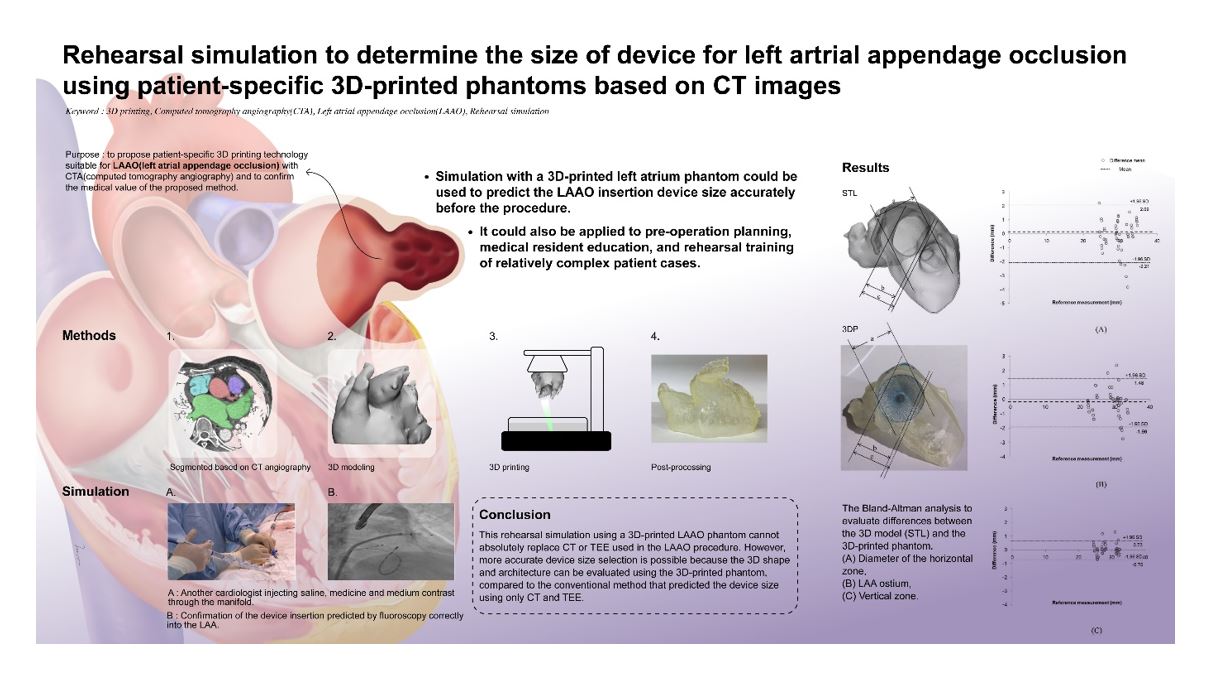
2.6 Accuracy comparison between the STL model and the 3D-printed phantoms
The 3D-printed phantom was printed based on the STL model. To compare the accuracy of each 3D-printed phantom with that of the STL model, the same landmarks of three different locations were measured by two observers. In addition, each observer measured each of them thrice, for a total of 180 times (Fig. 5), using Vernier calipers. A Bland-Altman analysis was used to evaluate the accuracies between the STL model and printed phantom (Fig. 6). Paired t-tests were performed to statistically compare the differences between the STL model and the 3D-printed phantom using the SPSS software (version 25.00; IBM Corp., Armonk, NY, USA).
2.7 Rehearsal simulation with 3D printed LAAO phantom
After producing the 3D-printed LAAO rehearsal phantom, a cardiologist simulated LAAO with the phantom. The clinician predicted the size of the LAAO device in the phantom simulation before the procedure and confirmed whether or not the size of the device used for the actual patient procedure was matched. In addition, the location and shape of the anatomical structures around the LAA were also confirmed (Fig. 7).