3.1. Characterizations of photocatalysts
Figure 1 shown the XRD patterns of as − synthesized ZIS, ZFO, and ZIS/ZFO composites. For the pristine ZIS and ZFO samples, the diffraction peaks could be indexed to hexagonal ZIS (JCPDS: 65 − 2023) (Mu et al. 2020) and cubic ZFO (JCPDS: 77 − 0011) (Cai et al. 2016), respectively. The characteristic peaks located at 2θ = 21.3°, 27.6°, and 47.4° were attributed to the (006), (102), and (110) planes of ZIS, and the peaks of ZFO at 29.8°, 35.1°, 42.7°, 56.5° and 62.1° were corresponded to the (220), (311), (400), (511), and (440), respectively. From the XRD patterns of ZIS/ZFO samples, the characteristic peaks of ZIS could be clearly observed, suggesting that ZIS nanosheets were successfully anchored to the ZFO rods. Besides, it was obvious that the peak intensity of (311), (511), and (440) facet for ZFO gradually increased with the increase of ZFO, which also implied that the two phases perfectly co − existed in the composites (Sultana et al. 2018).
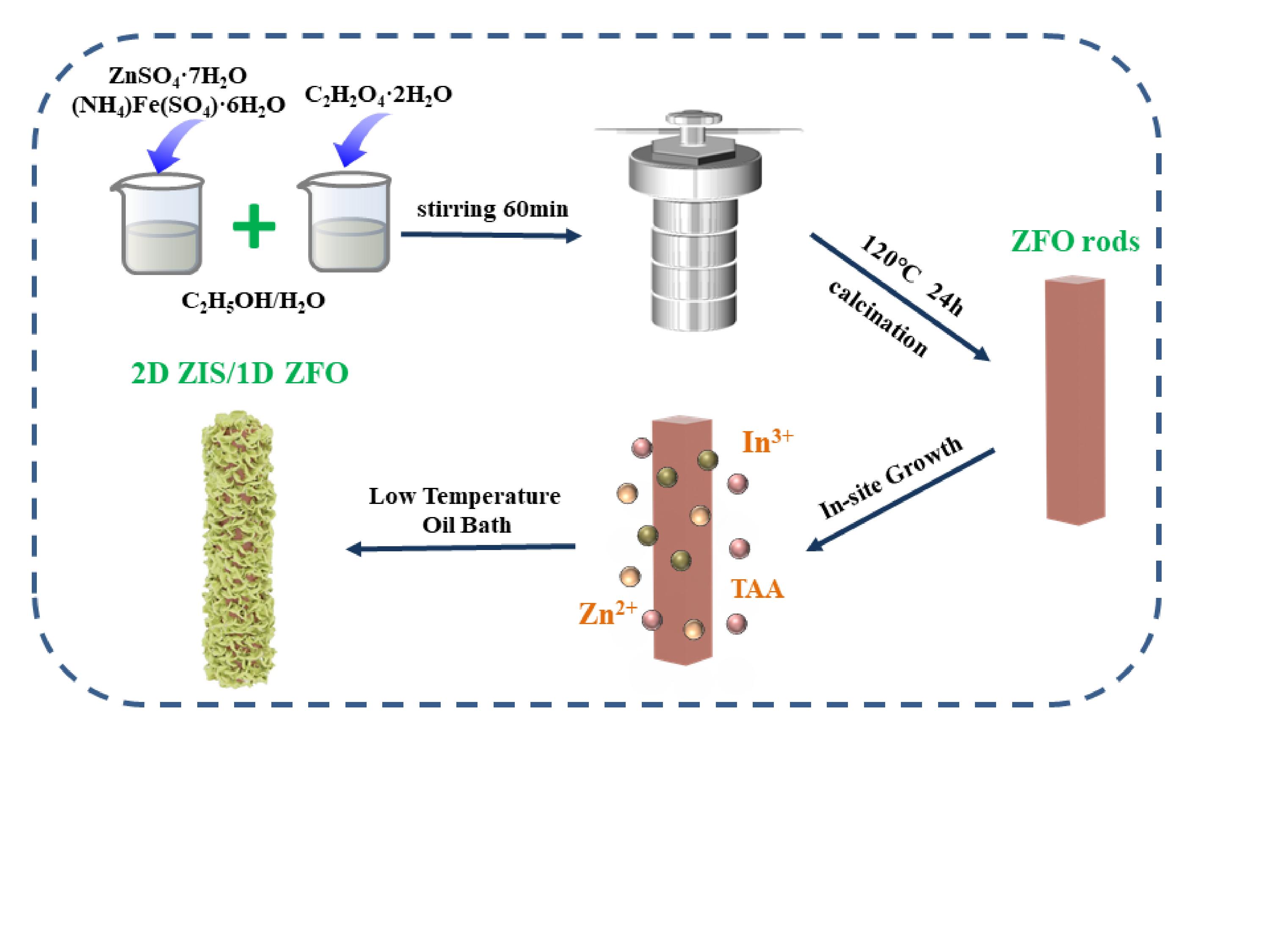
The morphologies and microstructures of resultant samples were further investigated by SEM and TEM and the results were depicted in Fig. 2a ~ g. Pristine ZFO shown a regular rod structure with width size of 2 ~ 4 µm (Fig. 2a and b). It could be observed from Fig. 2c and d that pristine ZIS possessed a flower − like structure composed of a large number of nanosheets. Figure 2e and f displayed the SEM and TEM pictures of ZIS/ZFO − 2 composite, and it was easy to see that ZIS nanosheets were uniformly and tightly dispersed around the ZFO rods. The close interfacial contact between the two structures contributed to the expansion of specific surface area and the formation of heterostructures, which leaded to excellent photocatalytic performance. In addition, the BET surface area of ZFO, ZIS, and ZIS/ZFO − 2 were determined to be 80.12, 64.32, and 118.24 m2·g− 1, respectively (Table 1), and the enhanced specific surface area also explained the thorough exposure of ZIS nanostructures after integration (Gao et al. 2022). Finally, the EDX elemental mapping analysis was obtained and the results were presented in Fig. 2g. The uniform elemental distribution of Fe, In, S, and Zn over ZIS/ZFO–2 sample further confirmed the successful combination of ZIS and ZFO.
Table 1
BET surface areas, pore volume, and average pore size of ZFO, ZIS, and ZIS/ZFO-2 composite.
| Catalyst | SBET (m2/g) | Pore volume (cm3/g) | Pore size (nm) |
| ZFO | 80.12 | 0.15 | 3.11 |
| ZIS | 64.32 | 0.12 | 6.97 |
| ZIS@ZFO − 2 | 118.24 | 0.14 | 6.78 |
To analyze the surface chemical composition of ZIS, ZFO and ZIS/ZFO–2 samples, XPS analysis was conducted. As could be seen from Fig. 3a, Zn 2p, Fe 2p, In 3d, S 2p, and O 1s appeared in XPS survey spectrum of ZIS/ZFO–2 composite, which was in line with EDX results. Figure 3b–d shown the high resolution XPS spectra of Fe 2p, In 3d, and S 2p, respectively. For ZIS/ZFO–2 composite, the characteristic peaks of Fe, In, and S elements located at 724.8 eV (Fe 2p1/2), 711.0 eV (Fe 2p3/2) (Guo et al. 2019; Yoo et al. 2017), 453.2eV (In 3d3/2), 445.7 eV(In 3d5/2) (Yang et al. 2017), 162.2eV (S 2p3/2), 163.7 eV(S 2p1/2) (Zeng et al. 2019a), respectively, could be found, which were basically consistent with literature date except for slight differences. In addition, there was a weak signal peak intensity of Fe in ZIS/ZFO–2 composite since the surface of ZFO was almost completely covered by ZIS nanosheets after integration. Notably, compared with two individual units, the binding energy of ZIS/ZFO–2 composite was significantly changed with a negative shift of Fe and positive shifts of In and S, which strongly proved that the transmission of photogenerated electrons caused the change of surface electron density under the action of intimate contact interface for different nanostructures. Meanwhile, according to the values of binding energy, it could be inferred that the transfer direction of photoexcited electrons was from ZIS to the surface of ZFO (Guo et al. 2019; Yu et al. 2017).
Figure 4a shown the optical absorption ability of ZIS, ZFO and ZIS/ZFO–2 samples. It could be observed from the UV–vis diffuse reflectance spectra that pristine ZIS and ZFO shown an intense light absorption with the band edge around 520 nm and 650 nm, respectively, and the corresponding bandgap energies were estimated by Kubelka − Munk equation to be about 2.33 and 1.94 eV, respectively (Fig. 4b). After growing ZIS nanosheets on ZFO, the obtained ZIS/ZFO samples exhibited the enhanced light absorption in the range of 250–650 nm by comparison with pure ZIS. The spatial distribution hierarchical structure was favorable for the reflection and scattering of light, which was responsible for the improvement of light absorption capacity over ZIS/ZFO composites (Chen et al. 2021). Additionally, the VB edge potential was measured to further determined the bandgap structure of synthesized sample. As presented in Fig. 4c, the obtained values for ZFO and ZIS were 0.68 and 1.62 eV, respectively. Therefore, the corresponding CB potential were calculated to be − 1.26 and − 0.71 eV, respectively. Combined with CB and VB potential positions obtained above, the energy band structures were shown in Fig. 4d. It could be seen that ZIS and ZFO exhibited mutually matched energy band distribution, which was conducive to the generation of heterojunctions and the improvement of photocatalytic performance.
3.2. Photocatalytic performance
The photocatalytic activities for RhB degradation of ZIS, ZFO and ZIS/ZFO composites were evaluated under visible light irradiation. As presented in Fig. 5a, there were relatively low photocatalytic RhB degradation efficiency for pristine ZFO (2.9%) and ZIS (24.4%). Oppositely, the removal efficiency of ZIS/ZFO composites were greatly improved, and 99.6% of RhB was completely degraded over ZIS/ZFO − 2 composite in just 8 min. The corresponding apparent rate constant of ZIS/ZFO − 1, ZIS/ZFO − 2, and ZIS/ZFO − 3 were 0.364, 0.695, and 0.226 min− 1, respectively (Fig. 5b), which were higher than that of ZFO and ZIS. In addition, the photocatalytic Cr(VI) reduction experiments were carried out to further verify the photocatalytic performance of as − synthesized photocatalysts and the results were presented in Fig. 5c. As expected, ZIS/ZFO − 2 composite shown a strongest Cr(VI) reduction potential with 96.6% removal efficiency during 20 min irradiation. To our knowledge, the excellent photocatalytic performance was superior to the most reported magnetic photocatalytic materials in the treatment of refractory pollutants in wastewater (Table 2). These results indicated that a close contact interface was formed between different nanostructures after growing ZIS nanosheets on ZFO, which induced the generation of abundant heterojunctions and accelerated the separation of photoexcited electrons and holes, thus improving the photocatalytic capacity. Besides, the reusability and stability of ZIS/ZFO − 2 composite was checked by recycling experiments for four times, and the result was presented in Fig. 5d. The removal efficiency of RhB over ZIS/ZFO − 2 composite did not decrease obviously after four cycles, which also confirmed that the prepared photocatalysts were basically stable in practical application process.
Table 2
Comparison of photocatalytic capacity with other previously reported photocatalysts for removal of refractory pollutant in recent years.
| Photocatalysts | Catalyst dose | Target pollutant | Reaction conditions | Degradation efficiency | Refs. |
| Fe3O4/BiOBr | 0.3 g/L | RhB | 100mL 20mg/L + 500W Xe lamp | 99.6% in 140 min | (Li et al. 2019) |
| ZnFe2O4/g–C3N4 | 3.3 g/L | RhB | 150mL 20mg/L + 500W Xe lamp | 98% in 60 min | ( Renukadevi and Jeyakumari 2020) |
| ZnFe2O4/Na–bentonite | 1 g/L | RhB | 100mL 10mg/L + 350W Xe lamp | 93% in 120 min | (Guo et al. 2019) |
| Pd/ZnFe2O4/ g–C3N4 | 0.2 g/L | RhB | 100mL 10mg/L + 300W Xe lamp | 95% in 60 min | (Zhang et al. 2020) |
| Fe3O4/FeWO4 | 1 g/L | Cr (VI) | 300mL 15mg/L + 350W Xe lamp | 99% in 100 min | (Ge et al. 2021) |
| Fe3O4@ZnxCd 1−xS | 0.2 g/L | Cr (VI) | 50mL 5mg/L + 1500mW·cm2 Xe lamp | 90% in 35 min | (Zhang et al. 2018) |
| Fe3O4@SiO2/Bi2WO6 − xF2x | 1 g/L | Cr (VI) | 100mL 50mg/L + 500W Xe lamp | 100% in 90 min | (Guo et al. 2019) |
| ZIS/ZFO | 0.2 g/L | RhB | 50mL 20mg/L + 300W Xe lamp | 99.6% in 8 min | This work |
| ZIS/ZFO | 0.3 g/L | Cr (VI) | 50mL 10mg/L + 300W Xe lamp | 96.6% in 20 min | This work |
The magnetic behaviors of ZFO and ZIS/ZFO − 2 photocatalysts were analyzed by vibrating sample magnetometry (VSM). As shown in Fig. 6a, the magnetization curves of ZFO and ZIS/ZFO − 2 samples passed through the coordinate origin, implied that they belonged to typical soft magnetic materials superparamagnetic properties (Wu et al. 2016). Besides, although the saturation magnetization of ZIS/ZFO − 2 composite was slight lower than that of bare ZFO, it could still satisfy the effective separation of photocatalysts in the reaction system. It could be clearly seen from the inset of Fig. 6a that ZIS/ZFO − 2 photocatalyst in the reaction system was quickly attracted to the magnet and the solution returned to transparency in a short time. The results indicated that the magnetic ZIS/ZFO − 2 composite was easy to recycle from the aqueous solution.
In order to explore the lifetime and transfer resistance of photogenerated charges during the photocatalytic process, electrochemical impedance spectroscopy (EIS) of ZFO and ZIS/ZFO − 2 samples were employed. As depicted in Fig. 6b, the Nyquist plots of EIS suggested that ZIS/ZFO − 2 composite has a smaller arc radius than bare ZFO, indicating a lower charge transfer resistance of ZIS/ZFO − 2 due to the effective charge separation (Ma et al. 2019; Zeng et al. 2019b). Meanwhile, the transient photocurrent response was measured to analyze the interfacial charge separation dynamics. It could be clearly seen from Fig. 6c that ZIS/ZFO − 2 composite exhibited about 2.2 times enhanced photocurrent response intensity after growing ZIS nanosheets on ZFO, which also implied a higher separation efficiency and longer lifetime of photogenerated e−–h+ pairs (Meng et al. 2018). These mutually compatible results were consistent with the remarkable photocatalytic performance of ZIS/ZFO–2 composite.
In order to elucidate the proposed mechanism of photocatalytic RhB degradation process over ZIS/ZFO–2 composite, radical trapping experiments were performed. AO (0.01M) and BQ (0.02) were added to capture h+ and •O2−, respectively (Chen et al. 2019; Chen et al. 2020). As shown in Fig. 6d, there was a distinct inhibitory effect on the removal efficiency of RhB in the presence of different scavengers, indicating the existence of h+ and •O2− in the photocatalytic process. Concretely, when AO and BQ were added into solution, the removal efficiency of RhB decreased from 99.6–75.9% and 29.6%, respectively. This phenomenon suggested that h+ radicals gave a minor contribution, while •O2− played a crucial role in the oxidation of RhB. Therefore, based on the above analysis, a direct Z − scheme charge transfer mode of ZIS/ZFO − 2 composite was proposed and elucidated schematically in Fig. 7. Under visible light irradiation, ZIS and ZFO were simultaneously excited to produce e− and h+ on the CB and VB. Then, the photogenerated e− located on CB of ZIS transferred rapidly to VB of ZFO and consumed h+. As a result, the retained photogenerated h+ in the VB of ZIS with strong oxidation potential could directly oxidized RhB, while the remaining photogenerated e− in the CB of ZFO shown a strong reduction effect on the conversion of O2/•O2− or Cr(VI)/Cr(III). Ultimately, the photogenerated e−−h+ pairs in ZIS/ZFO − 2 composite were effectively separated by Z − scheme heterojunction.