3.1 Schematic illustration of fabricated BNPC as supercapacitor electrodes
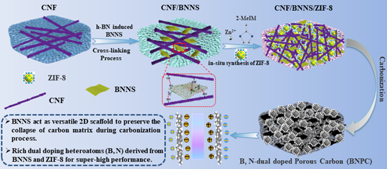
The schematic shown in Fig. 1 represents the process for fabrication of BNPC electrodes from CNF, BNNS, and ZIF-8. Herein, CNF prepared from wheat straw pulp fibers via an integrated method possesses excellent physicochemical properties, facilitating CNF to form uniform 3D cross-linking structure during the process, as shown in Fig. 1 and Fig. S1. BNNS is prone to uniformly contact with CNF scaffold to form 3D CNF/BNNS hydrogel after in-situ preparing BNNS within CNF hydrogel, during which BNNS acts as B/N dopants and structural stabilizer of CNF scaffold (Wang et al., 2019a). Thanks to the rich functional groups and high specific surface area of CNF, the hydroxyl groups and amino groups within BNNS can be intimately interacted with cellulose skeleton through hydrogen bonds between functional groups to fabricate a stable and strong 3D CNF/BNNS hydrogel (Chen et al., 2017).
During the freeze-drying process, CNF/BNNS framework should be immediately frozen using liquid nitrogen to maintain the 3D CNF/BNNS skeleton structure (Chen et al., 2017). Then 3D CNF/BNNS aerogel was used to sufficiently adsorb and anchor the ZIF-8 precursors of Zn ions and 2-MeIM, followed by in-situ synthesizing dodecahedron ZIF-8 nanoparticles within uniform micropores and rich functional groups (hydroxyl and amino groups) of CNF/BNNS aerogel to fabricate 3D porous CNF/BNNS/ZIF-8 precursor. The prepared ZIF-8 nanoparticles exhibited uniform and homogeneous dodecahedron morphology as shown in Fig. S2.
Once subjected to the modified two-stage carbonization process, CNF/BNNS/ZIF-8 precursor was transferred into a porous carbon substrate. During which, 2-methylimidazole in ZIF-8 was decayed at around 500°C to introduce boron-nitrogen dopants into the porous carbon structure. When temperature surpass 800°C, the carbon substrate becomes more porous and rough where Zn2+ within ZIF-8 NPs was reduced into metal zinc (Zn0) and then vaporized for pore generation (Wang et al., 2018). Then, the prepared carbon substrate was washed with a 3.0 M H2SO4 solution to further remove zinc element and other contaminants to obtain boron and nitrogen co-doped hierarchical porous carbon (BNPC) for supercapacitor electrodes.
Herein, the hypotheses of this study are as follows: (1) CNF acts as versatile supports of 2D BNNS to fabricate CNF/BNNS aerogel with highly porous 3D structure; (2) BNNS/CNF with cross-linking structure acts as a versatile 2D scaffold to stabilize the carbon matrix during carbonization process; (3) CNF/BNNS framework provides uniform porous structure for sufficient adsorption of ZIF-8 precursors and in-situ preparation of ZIF-8; (4) Abundant dual doping heteroatoms (B, N) derived from BNNS and ZIF-8 introduced into BNPC hierarchical porous structure can greatly enhance the electrochemical capacitive performance; (5) BNPC assembled supercapacitors perform advanced electrochemical performance, thanks to the synergistic effect of CNF, BNNS, and ZIF-8.
3.2 Structure and morphology analyses of BNPC and NPC samples
The morphological characterization of BNPC and NPC samples is illustrated in Fig. 2, Fig. S2 and S3. It showed that all BNPC samples exhibit an irregular 3D hierarchical porous network structure, and played a key role in facilitating improved electron constraint and ionic diffusion during supercapacitor applications (Lamm et al., 2021). Figure 2(b)-(d) reveals that the microstructure and mesoporous configuration of carbon materials increased with BNNS addition. Besides, BNPC exhibited a rough surface with few hollow channels and micropores along with BNNS addition, which would have positive impact on the electrochemical performance.
Moreover, BET studies have also been carried out given in Fig. 4(f), Table S1, and Fig. S4, which showed that all of the BNPC samples possessed highly porous structure and that BNP-2 had a highest SBET of 505.4 m2/g and Vpore of 0.40 cm3/g, which may be attributed to the fact that BNNS nanosheets were successfully embedded into the 3D cross-linking structure of CNF, resulting in an improved porous steric structure, but when more BNNS was in-situ prepared into CNF network at a CNF/BNNS of 1:3, partial porous structure of CNF network would be blocked by BNNS sheets, in addition, BNNS was also gradually accumulated along with the CNF frame when CNF/BNNS ratio was increased to 1:3, thus leading to a dense and compact structure of BNNS/CNF nanocomposites and a decreased porosity, as shown in Fig. 2(d) and Table S1. Similarly, Chen and co-workers prepared 3D-C-BNNS supported nano-structured cellulose via heat transfer nano-heterojunction and also found that BNNS with suitable dosage would be beneficial to the porosity, but an excess BNNS dosage would impair the porous structure (Chen et al., 2017).
The intertexture of rigid BNNS within CNF network would regulate and control the growth of ZIF-8 nanoparticles. A high-resolution image of BNPC-2 was shown in Fig. S2(a), in which showed that BNNS was clearly observed within CNF network, ZIF-8 nanoparticles were also successfully synthesized and restricted within the porous structure of CNF/BNNS nanocomposites, thus controlling the particle size of ZIF-8 nanoparticles. After the two-stage carbonization process, ZIF-8 nanoparticles were partially removed and the initial 3D porous network structure of CNF/BNNS/ZIF-8 nanocomposites was maintained, as clearly shown Fig. 2 and Fig. S2(b) of the side view of BNPC-2 sample, which was corresponding to the previous literature (Chen et al., 2019). Evidently, the EDX elemental conformation of BNPC-2 indicates that B, C, N, and O elements were evenly distributed within BNPC samples, as shown in Fig. S3 and Table S1, indicating that BNPC samples have been well heteroatoms doped with sufficient N and B elements that are necessary for high electrochemical performance, as shown in Fig. 2(e).
TEM images of BNPC-2 sample with different resolutions were well illustrated in Fig. 3 to better understand the hierarchical porous structure and topographical features of prepared carbon materials. Figure 3(a) showed that the rod-like CNF were tightly connected with laminar BNNS to form CNF/BNNS nanocomposites, which was well corresponding to the SEM result shown in Fig. S2(a). The high temperature treatment of two-stage carbonization process hardly changes the original CNF/BNNS/ZIF-8 superstructure but maintains its original hierarchical porous structure. The laminar BNNS with different sizes were also observed in Fig. 3(b), indicating the existence of exfoliated BNNS within BNPC framework. The well dispersed mesoporous and microporous within BNPC-2 substrate were clearly exhibited in Fig. 3(c) and Fig. 3(d) at high magnification of TEM images, demonstrating a hierarchical porous structure of BNPC.
3.3 Characterization of BNPC and NPC carbon samples
Figure 4(a) showed the XRD patterns of NPC and BNPC samples to characterize their crystalline structure. It illustrated that the XRD patterns of each carbon sample demonstrated a broad peak at approximately 23º, which is corresponded to the (002) plane of typical carbon patterns (Peng et al., 2018). After adding BNNS, a new characteristic sharp intense peak at approximately 2θ = 26.6° was observed, which is ascribed to BNNS (Maity et al., 2019). Moreover, the peak of carbon graphite elevated at approximately 43º after carbonization was corresponding to the (100) plane (Patil et al., 2020). All the peaks in XRD patterns confirmed that BNNS have been successfully interacted with the nanocellulose skeleton to form 3D network porous structure. With the addition of BNNS into CNF substrate of CNF/BNNS nanocomposites, a stronger intensity of the (100) characteristic peaks was observed after the two-stage carbonization process, verifying the graphitization phenomenon of CNF/BNNS/ZIF-8 nanocomposites through dual synergetic boron and nitrogen co-doping, which would greatly facilitate the graphitization degree through the inducing effect of co-dopants (Ferrari, 2007).
The increased graphitic carbon within BNPC samples can effectively increase the electron transfer and conductivity, which would further enhance the charge transport rate during the electrochemical process for improved supercapacitor performance (Zou et al., 2019). In addition, Raman spectroscopy has been habitually used to distinguish and calculate the number of layers, doping level, and disorder structure in graphite-based nanomaterials (Ferrari, 2007). As shown in Fig. 4(b), both D and G-bands (known as the disorder or the defect band and graphitic band respectively) are clearly presented in Raman spectra. All of the carbon samples showed D and G-bands appearing at around 1330 cm− 1 and 1560 cm− 1 respectively (Deng et al., 2019), which was noted that all carbon samples gave evidence of characteristic disorder carbon and graphitic carbon. In addition, the intensity ratio of IG/ID indicated the graphitic degree of carbon materials (Lin et al., 2015). The results showed that IG/ID intensity ratio of carbon samples (NPC, BNPC-1, BNPC-2, and BNPC-3) increased from 0.82 to 0.93, indicating high graphitization degree for enhanced electrochemical performance. These results are also consistent with the XRD results demonstrated in Fig. 4 (a). This phenomenon may be attributed to a significant heteroatom N and B dopants within the hierarchical porous 3D network (Maity et al., 2019; Puziy et al., 2020).
XPS analyses (Fig. 4(c)-(f)) are performed to identify the chemical composition and surface characteristics of these carbon samples. From Fig. 4(c), it is observed that four peaks centered at 190, 285, 401, and 532 eV, are referred to B1s peak, C1s peak, N1s peak, and O1s peak, respectively (Kim and Yang, 2013). Table S1 summarizes the surface chemistry and elemental compositions of these carbon samples, which verified that boron and nitrogen heteroatoms have been successfully co-doped within BNPC samples, thus would effectively facilitate the subsequent improved pseudocapacitance performance of BNPC based supercapacitors (Costentin et al., 2017). Besides, the zinc species within ZIF-8 nanoparticles were removed during the heating and its following acidic washing process (Li et al., 2018), which was also consistent with the elemental EDS mapping results shown in Fig. S3 and Table S1. The detailed B1s spectra of BNPC-2 sample were given in Fig. 4(d) to analyze its type and functional groups. The fitting of B1s peak can be divided into parallel B-C (190.7 eV) and B-N (189.9 eV) bonds (Bian et al., 2018). The complex N1s XPS spectra of the BNPC-2 (Fig. 4(e)) were corresponding to C-N-B (397.9 eV), N-6 (399 eV), and N-5(400.2 eV), respectively (Zou et al., 2019).
Figure 4(f) reveals the specific surface area and hierarchical porous structure of prepared BNPC carbon materials interpreted by Brunauer-Emmett-Teller (BET) experiments. It was found that the green curve behaved type I adsorption isotherms for the NPC sample, indicating the presence of abundant micropores and some mesopores, which may be attributed to the carbonization process of ZIF-8 nanoparticles within CNF/BNNS network to form micropores along with the vaporization of embedded Zn2+ species at a high temperature. As for N2 adsorption and desorption isotherm of BNPC-1, BNPC-2, BNPC-3 samples, the corresponding curves behave characteristic type IV adsorption isotherms, which were ascribed to the addition of BNNS, indicating an increased mesopore ratio within carbon substrate (Chen et al., 2019).
It should be noted that the H4 type hysteresis loop appeared in the BNPC-2 sample curve at the medium pressure range (0.45-1.0). The H4 type hysteresis loop is a combination of type I and type II adsorption isotherms, which is always appeared on adsorbents mixed with micropores and mesopores and solids with narrow pores, indicating that BNNS can act as steric flake skeletons to prevent the aggregation of CNF frame from the closely contiguous arrangement, thus resulting in long and narrow interconnecting channels within framework (Zou et al., 2019). When excessive BNNS was added, the flake might overlap with each other and the narrow mesopores would be blocked, as shown in Table S1. It indicated that BNPC-2 sample performs superior aspect ratio and porosity than NPC and other carbon samples. Most importantly, it is observed that the majority of pore sizes are in between 2–5 nm as shown in Fig. S4. Further, this is beneficial for fast diffusion of ions in the electrolyte to electrode surface and high adsorption of electrolyte ions during the electrochemical test process (Fu et al., 2018; Ratajczak et al., 2019).
3.4 Wettability analyses of BNPC and NPC carbon samples
The wettability of carbon based electrode plays a critical role in improving the supercapacitor performance (Wang et al., 2020), since high hydrophilicity of as-prepared electrode not only benefits the rapid ionic transportation between aqueous electrolytes and the inner porous structure of electrode, but also offers abundant electroactive sites for rapid adsorption/desorption of electrolyte ions when using an aqueous electrolyte. In this study, we first successively combined the three components of CNF, BNNS, and ZIF-8 to construct BNPC activated carbon with 3D hierarchical porous framework, during which, CNF acts as versatile scaffolds and endows BNPC with porous structure, ZIF-8 and BNNS provide BNPC with desirable B/N co-doped heteroatoms and graphitization structure during the two-stage carbonization treatment, thus guaranteeing the improved wettability property of BNPC based electrodes against KOH aqueous electrolyte. The KOH solution contact angles of each carbon sample recorded at 10 sec. are shown in Fig. 5.
As shown in Fig. 5(a), the contact angle of NPC is 34.4º, which is higher than that of BNPC samples (Fig. 5(b)-(d)) of 13.9º, 10.4º, 8.9º, respectively. As shown in Table S1 and Fig. S4, BNPC samples had an improved porosity and higher N and B heteroatoms co-dopant content than that of NPC sample without BNNS addition. It can be concluded that BNPC carbon substrates perform a higher hydrophilicity property against KOH electrolyte than NPC sample, and that the higher BNNS ratios (BNPC-2, BNPC-3) would contribute greater effect on the hydrophilicity (BNPC-1). There are two main reasons for explanation of the above phenomenon: 1) high porosity and specific surface area provide higher cavity and capillary force for efficient adsorption of aqueous KOH electrolyte; 2) higher B and N dopant content within carbon substrate can effectively improve the hydrophilicity of carbon substrate against aqueous KOH electrolyte, due to their natural hydrophilic attributes.
Interestingly, BNPC-3 sample with a CNF/BNNS ratio of 1:3 has the lowest contact angle of 8.9º but with a lower specific surface area and porosity than that of BNPC-2, indicating that BNPC possessed the highest wettability due to its highest N and B content (as shown in Table S1). However, it can be found that although the BNPC-3 sample showed best hydrophilicity ability with KOH electrolyte, which had a lower capacitance performance than that of BNPC-2, it may be ascribed to the deteriorated porosity of carbon structure, as shown in Table S1 and Fig. S4. The above result is corresponding to the previous report (Wang et al., 2019b). In conclusion, BNPC-2 sample derived from a CNF/BNNS ratio of 1:2 possessed a desirable 3D hierarchical porous superstructure and B/N co-dopant content, thus guaranteeing reasonable hydrophilicity against with aqueous KOH electrolyte for improved supercapacitor performance.
3.4 Electrochemical performance analyses of NPC and BNPC carbon electrodes
Carbon based electrodes derived from CNF/BNNS/ZIF-8 nanocomposites possess excellent three-dimensional B/N co-doped heterostructure, thus providing improved electrochemical sites and enhanced energy storage capability when they are assembled in supercapacitors. Figure 6 and Fig. S5 demonstrate the capacitive electrochemistry studies such as cyclic voltammetry (CV), galvanostatic charge/discharge (GCD), specific capacity, and cycling stability of BNPC and NPC based on supercapacitor device tested in an aqueous 6.0 M KOH electrolyte. As shown in Fig. 6(a), all the carbon samples showed a nearly rectangular-like shape, indicating an electrical double layer capacitive (EDLC) behavior when assembled as electrodes (Fig. 6(a)) (Ratajczak et al., 2019). Furthermore, BNPC-2 was found to show a larger capacitive response area than other carbon samples, indicating a higher capacitance ability (Costentin et al., 2017).
In addition, the GCD studies within the range of -1 to 0 V at 1.0 A/g current density using an aqueous 6M KOH electrolyte are carried out for all carbon samples as shown in Fig. 6(b), indicating that all carbon based supercapacitors exhibited symmetrical triangle curves with slight distortion, verifying an EDLC behavior together with a little bit of pseudo-capacitance (Ma et al., 2019). BNPC based electrodes performed higher electrochemical capacity than that of NBC sample without BNNS addition. The excellent 3D porous structure and sufficient B/N co-dopants of BNPC samples contribute greatly to the improvement of electrochemical capacitance, as well as the charging-discharging property. Moreover, the BNPC-2 electrode assembled supercapacitor had the longest discharge time, indicating a highest supercapacitor performance. Therefore, various potential sweep rates and GCD curves for cycling CV analyses at a range current density based on BNPC-2 electrode were studied to evaluate the cycling stability during the charging and discharging process.
The gravimetric capacitance of BNPC and NPC carbon samples was calculated according to Eqs. (1) and summarized in Fig. S5(a). It was found that the specific capacitances of BNPC-2 are 433.4 F/g at 1.00 A/g and 362.16 F/g at 10 A/g respectively, which were much higher than the specific capacitance of NPC electrode (184.4 F/g at 1.0 A/g and 113.16 F/g at 10 A/g). The enhanced capacitance performance of BNPC-2 based supercapacitor could be contributed to the optimized hierarchical porous superstructure and the dual synergetic boron and nitrogen doping effect on its performance. Thanks to the versatile roles of CNF framework, BNNS, and ZIF-8 nanoparticles for the preparation of porous carbonaceous network within BNPC-2, and the efficient connections among carbonized BNNS, ZIF-8 and CNF based carbon fibers, as shown in Fig. 1 and Fig. S1, thus would greatly improve the sufficient absorption and fast diffusion/ transmission of electrolyte ions during the capacitance tests with advanced supercapacitor performance (Chen et al., 2018).
Moreover, the simultaneous doping of n-type and p-type dopants can also induce a redistribution of electrons, which could enhance the faradic redox reactions and lead to an extra pseudo-capacitance (Wu et al., 2019). The specific capacitance of sample BNPC-2 maintains about 83.6% of its initial capacitance with the current density increased from 1.0 A/g to 10 A/g as shown in Fig. 6(d), which is much higher than that of the single N doping sample NPC (61.4%). It has been reported that B doping can greatly improve the supercapacitor performance at high current density (Zhu et al., 2018). The GCD was also used to show the cycling performance of the BNPC-2 for the supercapacitor prototype (Fig. S5(b)). Furthermore, it can be observed that the BNPC-2 based electrode possesses exceptional charging-discharging cycles and improved capacitance stability, and that specific capacitance of BNPC-2 sample reaches about 95% even after 2000 cycles at 1.0 A/g.
For commercial purposes, the asymmetric supercapacitor prototype device was assembled with BNPC-2 electrode and measured with a two-electrode system in 6.0 M aqueous KOH electrolyte, as shown in Fig. 7. Figure 7(a) represents the CV of BNPC-2 based supercapacitor with a scan rate from 5 to 200 mV/s. It can be noted that all CV curves retained an almost rectangular shape, indicating an ideal efficient EDLC property (Lin et al., 2015). All BNPC-2 samples exhibited rectangular nature of curves as shown in Fig. 7(b), which may be attributed to the EDLC behavior. Clearly, a small IR drop was investigated in the charge-discharge curves, which may be ascribed to the N/B heteroatom doping effect (Wu et al., 2019).
Figure 7(c) showed a trend of specific capacitance of BNPC-2 based supercapacitor evaluated from GCD curves at different current densities. It was found that BNPC-2 sample exhibited a highest specific capacitance of 245.2 and 229.2 F/g at 1.0 and 20 A/g, respectively. In addition, Fig. 7(d) showed a desirable cycling performance of BNPC-2 based supercapacitor even measured at a high current density of 1.0 A/g, and found that just 9.54% of the original capacitance was loss after 5000 cycles. Furthermore, the Ragone plot of BNPC-2 assembled supercapacitors was shown in Fig. S6, in which the BNPC-2 based EDLC device performed excellent 34.06 and 25.61 Wh/kg energy density even at 1000 and 20 kW/kg power density, respectively. To further evaluate the performance of the synthesized BNPC samples, EIS measurements were conducted. The fitted Nyquist plots and the equivalent circuit were shown in Fig. S7.
In addition, the comparisons of specific capacitance of previously reported carbon-based electrodes and BNPC-2 based electrodes have been listed in Table S2, in which showed that BNPC-2 based supercapacitor (this study) serves a relatively high energy density of 433.4 F/g at 1 A/g, compared with other reported results. The advanced supercapacitor performance can be ascribed to the fact that: CNF acts as versatile green supports of 2D BNNS, have a superior ability to fabricate 3D porous CNF/BNNS scaffold to stabilize the carbon matrix during the two-stage carbonization process, and that BNNS/CNF/ZIF-8 nanocomposites impart hierarchical porous superstructure of BNPC with sufficient boron and nitrogen dual dopants derived from BNNS and ZIF-8, thus providing BNPC based supercapacitor with high amount adsorption of electrolyte, high transmission rate of electrolyte ions, as well as high cycling stability, thanks to the synergistic effect of CNF, BNNS, and ZIF-8. In conclusion, the prepared hexagonal boron nitride nanosheets added into the CNF 3D framework can be an effective way to produce carbon electrodes with a high electrochemical performance.