Figure 1a-e provides a comprehensive understanding of the morphology and structural characteristics of CDs. In Fig. 1a, the HRTEM image displays a distribution of spherical CDs. Figure 1b, shows resolved lattice fringes with specific interplanar distance of 0.34 nm, which corresponds to 002 plane of sp2 graphitic carbon [25]. The lateral size distribution histogram in Fig. 1c indicates that the average size of CDs is 2.4 nm. The spotty ring Selected Area Electron Diffraction (SAED) pattern describes the polycrystallinity, emphasizing the presence of a graphitic centre. The XRD pattern in Fig. 1d, complements the above findings by showing broad diffraction peak at 23.2° corresponding to (002) plane, which represents the amorphous or turbostratic graphitic structure of CDs. The broad peak indicates that the CDs have a short-range order, contributing to amorphous nature of CDs [26, 27]. Additionally, the Raman spectrum in Fig. 1e indicates D and G bands at 1368 cm− 1 and 1567 cm− 1, respectively. The D band represents the presence of disorders associated with CDs, and G band signifies the sp2 hybridized carbon structure [28]. The Raman spectrum indicates the presence of both disorder and graphitic carbon structure [29]. The ID/IG ratio was found to be 1.18, which indicates the graphitic structure of CDs [30].
The functional groups and elemental composition of CDs are studied using FTIR and XPS. The FTIR spectrum in Fig. 1f shows the functional groups present in CDs. The broad peak at 3499 cm− 1 and sharp peak at 1414 cm− 1 correspond to the stretching vibration of O-H bond [31]. Stretching vibration of C-H bond, associated with alkyne and alkane groups, is detected at 3182, 2968, and 2871 cm− 1 [21]. The peak around 1695 and 1659 cm− 1 is attributed to the stretching vibration of C = O bond [32]. The presence of amine group was obtained by peak at 1561 cm− 1 which is due to N-H bond vibration [21]. The formation of an amine bond confirms the condensation and dehydration reactions between carbon and nitrogen sources [13]. XPS measurements were conducted to further elucidate the composition of CDs. The prominent peaks observed in Fig. 2a at 286, 532, and 399 eV correspond to the C1s (84.5%), O1s (14.8%), and N1s (0.7%) regions, respectively. High-resolution deconvolution of the C1s XPS spectrum in Fig. 2b revealed distinct peaks at 284.7, 285.9, and 288.6 eV, corresponding to C-C, C-N, and C = O bonds [33]. The O1s spectra (Fig. 2c) depicted oxygen in various forms, such as C = O and C-O-C, represented by peaks at 531.0 and 532.5 eV [34]. Deconvolution of the N1s spectra (Fig. 2d) disclosed the presence of pyridinic and pyrrolic nitrogen at 399.0 and 399.8 eV, respectively [35]. Examination of XPS and FTIR analysis confirms the existence of nitrogen, carbon, oxygen, and hydrogen-containing functional groups bonded on the surface of CDs, encompassing hydroxyl, carboxyl/carbonyl, amide, and amine moieties. These functional groups have trap states that would trap photoexcited electrons and P3HT contributes to the passivation of electron traps within the functional groups [36].
The FTIR spectra for P3HT and the CDs/P3HT composite is given in Fig. 3a. The peaks at 3485 and 3019 cm− 1 correspond to the OH stretching and C-H bond of hexyl groups, respectively [37, 38]. Peaks at 2971 and 2878 cm− 1 arise from symmetric and asymmetric vibrations of the aliphatic C-H bond [39]. The peaks at 1725, 1490, and 1369 cm− 1 are attributed to C = O stretching of the ester group, C = C stretching of the symmetric ring, and the C-S thiophene peak of P3HT, respectively [37, 38]. Peaks at 1604 and 1221 cm− 1 are associated with carboxylic groups. The peaks at 1268, 1160, and 1096 cm− 1 correspond to C-O vibration of aromatic ester, symmetric C-O-C bond vibration, and C-S stretching vibration, respectively [40]. In the CDs/P3HT composite, these peaks are nearly identical but with increased intensity and shifts in the C-H bond peak to 2968 cm− 1, the C = O bond peak to 1606 cm− 1, and the C-O bond peak to 1265 cm− 1. These shifts and the increase in peak intensity confirm the formation of a composite through bonding between CDs and P3HT. The UV-Vis and PL spectra of CDs are given in Fig. 3b, c. The UV-Vis peak indicates a weak absorption peak at 349 nm and a strong absorption peak at 250 nm arising due to n – π* electronic transition of C = O or C = N bonds and π – π* electronic transition of sp2 hybridized aromatic carbon [3, 41]. The bandgap of CDs was found to be 3.19 eV using tauc plot. CDs exhibited broad emission around 450 nm when excited at 350 nm wavelength, which originated from the band-to-band transition in conjugated π domains within sp2 carbon [5]. The broad emission spectrum confirms that the CDs have intermediate defect states. The rise in intensity and the red shift in the absorption peak, transitioning from 450 nm for P3HT to 453 nm for CDs/P3HT in Fig. 3d, signifies that the incorporation of CDs into the P3HT matrix improves the conjugation structure, leading to enhanced π – π* transaction [42]. This enhancement is confirmed by FTIR analysis, which shows increased intensities of the carboxylic group peaks in CDs/P3HT at 1268 and 1604 cm− 1. CDs/P3HT showed a narrow bandgap of 2.3 eV. Concurrently, a reduction in intensity is observed in the PL spectrum in Fig. 3e, indicating a supramolecular interaction between CDs and P3HT through π-π stacking of their conjugated structures [43]. This interaction promotes electron delocalization and facilitates effective charge transfer between CDs and P3HT by generating intermediate states through the overlapping of π orbitals, leading to fluorescence quenching [24, 44].
Device Performance
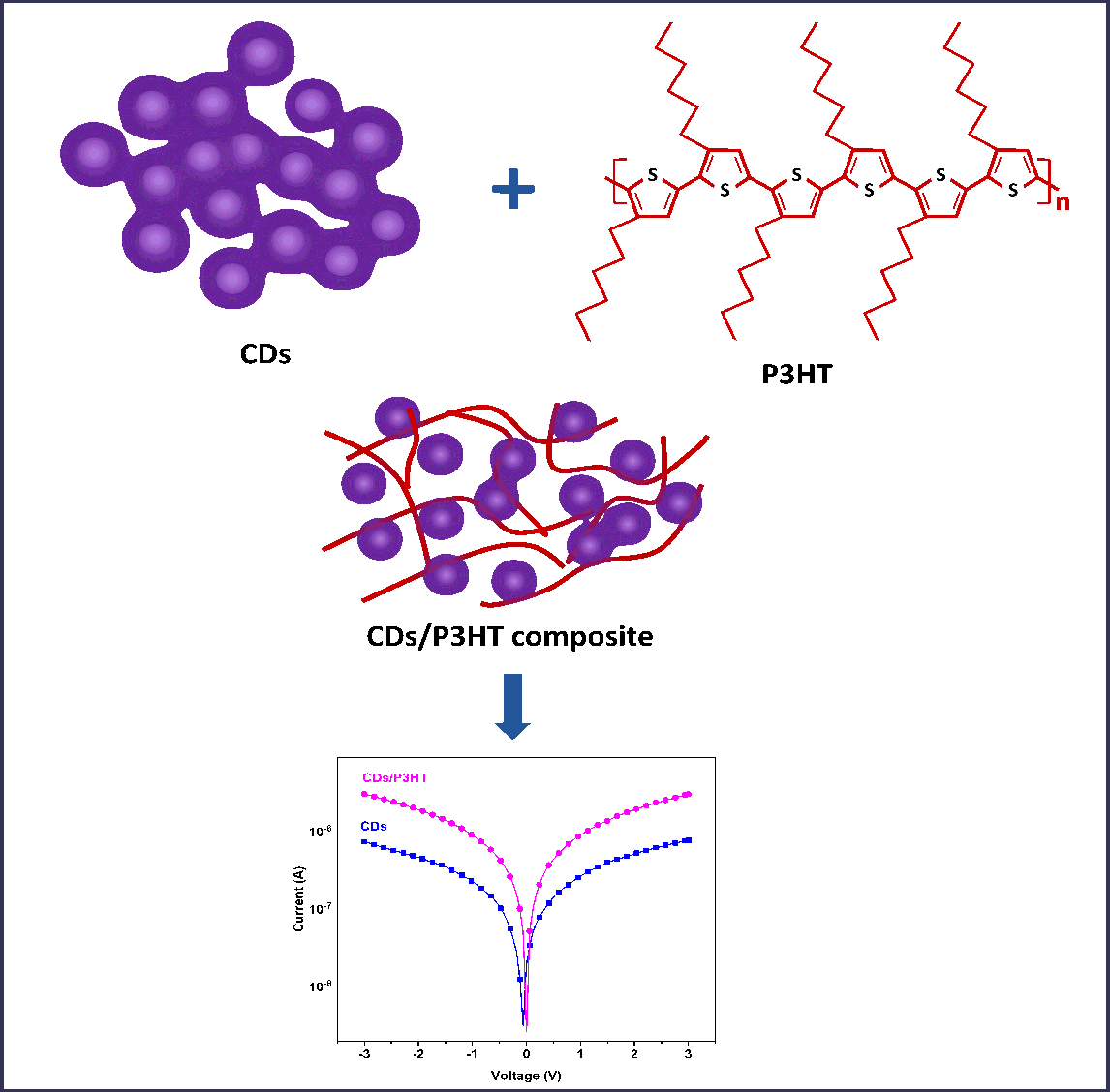
The current-voltage (I-V) curves for both CDs and CDs/P3HT PDs are given in Fig. 4a and b. These I-V measurements were conducted in visible, 365, and 254 nm regions, employing ITO as the electrode with a fixed bias of 3V. Here, the CDs and CDs/P3HT generate Schottky contact with ITO electrode, thereby producing a linear curve during light illumination. The CDs PD showed minimum dark current of 2.3 × 10− 9 A, while the photocurrent was 2.8 × 10− 8 A, 7.75 × 10− 7 A, and 3.77 × 10− 7 A under visible light, 365, and 254 nm, respectively. Interestingly, the CDs/P3HT PD demonstrates significantly higher photocurrent values of 3.9 × 10− 6 A, 3 × 10− 6 A, and 1.34 × 10− 6 A in the visible light, 365 and 254 nm regions, respectively, compared to the pure CDs PD in Fig: 4b. The observed rise in photocurrent can be attributed to the effective distribution of CDs/P3HT heterojunctions within the active layer, facilitating rapid exciton dissociation and preventing recombination [45]. In addition, the presence of P3HT improves electron transfer by mitigating electron trapping through passivation of functional groups, which is evidenced by changes in the chemical environment of carboxylic groups observed in FTIR spectra [36]. The extensive absorption spectrum of CDs/P3HT in Fig. 3c suggests its capability to detect wavelengths in both the UV and visible regions. The above results convey that the composite form of CDs with P3HT enhances the photocurrent of the PD.
The increase in photocurrent at the heterojunction can be understood through the electron transition mechanism using an energy band diagram. The energy band diagram in Fig. 5 is depicted using data reported earlier. Sofia Paulo et al. [46] found the highest occupied (HOMO) and lowest unoccupied (LUMO) states of CDs as -2.07 and − 5.13 eV, respectively through cyclic voltammetry. The HOMO and LUMO energy levels of P3HT are identified as 3.31 and 5.15 eV, respectively [47]. Under illumination with UV light, photogenerated electrons within CDs are excited to the LUMO of CDs, leaving behind holes in the HOMO level. The difference between the HOMO of CDs and the work function of ITO leads to a mismatch in energy levels, creating barrier that impedes hole extraction. By incorporating P3HT, which has a HOMO at 5.1 eV, the energy levels are better aligned, thereby enhancing hole extraction efficiency [48]. As a result, the photo induced electron-hole pairs are subsequently transported to the LUMO and HOMO levels of P3HT, respectively, and are collected through the ITO electrode, aided by an externally applied electric field. In CDs, the presence of surface defects and trap states in localized π – π* electronic levels accelerates recombination, resulting in broad photoluminescence [8]. This results in need for the implementation of a passivating and carrier transport layer that could suppress the recombination of photogenerated charge carriers [5, 9]. In this context, P3HT functions as a transport layer, establishing intermediate states via π – π interaction, resulting in improved energy band alignment when combined with CDs [20]. This configuration facilitates the efficient transport of photogenerated carriers from CDs to P3HT. Hence, it is understood that under illumination, CDs generate electron-hole pairs, which are efficiently transferred to P3HT through these intermediate states and are collected through the electrodes. Furthermore, P3HT plays a significant role in achieving visible light photodetection. The CDs/P3HT exhibit broad absorption in the visible region, and P3HT generates a higher number of charge carriers, contributing to an enhanced photocurrent in the visible region. As evident from the IV graph in Fig. 4b, the CDs/P3HT PD exhibit a larger photocurrent under visible light compared to 365 and 254 nm, aligning with the broad absorption characteristics of the CD/P3HT. Photo-induced holes in P3HT are transferred to CDs, inducing p-type doping. This process leads to an elevation of the built-in potential and junction field, facilitating effective charge dissociation in the heterojunction. As a result, holes move towards CDs, while electrons are transferred to ITO, ultimately enhancing the photocurrent.
The parameters of PDs including Responsivity (R), Detectivity (D), and photocurrent to dark current ratio (IP/ID) were calculated using equations (1–3) and listed in Table 1.
$$R=\frac{{I}_{Ph}}{PA}$$
1
$$D=R\sqrt{\frac{A}{2q{I}_{D}}}$$
2
$$Photo-dark current ratio=\frac{{I}_{Ph}}{{I}_{D}}$$
3
where, R is Responsivity in AW− 1, IPh is Photocurrent in A, P is incident power density in W/m2, A is area of PD in m2, D is Detectivity in Jones, q is the charge of an electron in C (1.602×10− 19 C) and ID is dark current in A [3].
The responsivity of PDs was calculated using Eq. (1). Responsivity gives the efficiency of a PD to convert photonic input into electrical output. The calculated responsivity of CDs/P3HT PD is 6.1 × 10− 3 AW− 1, 4.7 × 10− 3 AW− 1 and 2.10 × 10− 3 AW− 1 under visible light, 365 nm and 254 nm. Detectivity (D) is another critical parameter used to assess the PD's ability to detect optical signals, and it is calculated using the expression (2). The detectivity of CDs/P3HT PD is 0.69 × 10⁹, 0.53 × 10⁹, and 0.23 × 10⁹ Jones. Most importantly, the CDs/P3HT PD shows a high IPh/ID using Eq. (3) around 155, indicating better noise rejection ability of the PD. This large photoresponsivity of CDs/P3HT compared to CDs PD is a consequence of the efficient charge transfer between CDs and P3HT, leading to spatial separation of generated electrons and holes. The CD/P3HT PD exhibits high responsivity and detectivity in visible light because, despite the CDs being dispersed across the surface of P3HT, a large portion of P3HT is exposed to photo irradiation, yielding higher values [5]. From Fig. 4c, it is evident that CDs/P3HT PD exhibit photoresponse. Figure 4d illustrates that the responsivity and detectivity of CDs/P3HT PD gradually increase as the concentration of CDs increases. Table 2 shows the enhanced photoresponse of CDs/P3HT PD relative to other results.
Table 1
CDs/P3HT PD parameters for different wavelengths.
| | Dark Current (nA) | Photocurrent (A) | Responsivity (A/W) | Detectivity (Jones) | IP/ID |
| Visible Light | 365 nm | 254 nm | Visible Light | 365 nm | 254 nm | Visible Light | 365 nm | 254 nm | Visible Light | 365 nm | 254 nm |
| CDs | 2.36 | 0.028×10− 6 | 0.77×10− 6 | 0.37×10− 6 | 0.044×10− 3 | 1.21×10− 3 | 0.58×10− 3 | 0.14×10⁸ | 0.39×10⁹ | 0.19×10⁹ | 12 | 329.1 | 160 |
| CDs/P3HT | 19.6 | 3.92×10− 6 | 3.05×10− 6 | 1.34×10− 6 | 6.12×10− 3 | 4.76×10− 3 | 2.10×10− 3 | 0.69×10⁹ | 0.53×10⁹ | 0.23×10⁹ | 199.9 | 155.5 | 68.63 |
Table 2
A comparison of the photoresponse from previously published studies with our results.
| Material | Synthesis method | Detection range | Bias | Photocurrent | Responsivity | Ref |
| p-CDs@PVA | Hydrothermal | 250–310 nm | - | - | 2.5 mAW− 1 | [49] |
| GQD | Hydrothermal | DUV 254 nm | 5 V | 8 × 10− 9 A | 2.1 mAW− 1 | [11] |
| PANI-GQD | Microwave-assisted hydrothermal treatment | 405 nm | 1 V | 52.66 nA | 8.9 µAW− 1 | [50] |
| 532 nm | | 23 nA | 1.05 µAW− 1 |
| N-GQDs | Microwave assisted synthesis | UV - NIR | - | - | 325 V/W | [51] |
| PPy-GQD composite | Hydrothermal | 265 nm | 1V | 2.9 µA | 0.36 µAW− 1 | [14] |
| 355 nm | | 18.7 µA | 2.33 µAW− 1 |
| CDs/PVA | Hot plate method | 254 nm | 3V | 1.12 µA | 1.7 mAW− 1 | [3] |
| 365 nm | | 0.85 µA | 1.3 mAW− 1 |
| CDs/P3HT | Microwave method | UV-Vis | 3V | 3.9 µA | 6.12 mAW− 1 | This work |