The potential for lightweighting of railway axles was investigated to primarily reduce the unsprung mass of rail vehicles. The reduction of unsprung mass equates to an overall lighter train which will help to reduce: track damage, energy consumption and total operating costs. This paper presents the design of a lightweight multifunctional hybrid metallic-composite railway axle utilising coaxial skins. The lightweight axle assembly comprises a carbon fibre reinforced polymer composite tube with steel stub axles bonded into either end. The structural hybrid metallic-composite railway axle is surrounded by coaxial skins each performing a specific function to meet secondary requirements. These include fire and ballast skins to protect the axle core. An outer pigmented layer provides visual identification of the axle class, along with protection against environmental agents. Integrated into the railway axle is a structural health monitoring layer to provide feedback on the integrity of the composite tube and adhesive bonds during the operating life. A tether assembly acts as a failsafe against wheel detachment resulting from catastrophic axle damage. The optimised hybrid metallic-composite railway axle design concept has a mass of 200 kg representing a reduction of 50% over the solid steel version.
Research
Design of A Lightweight Multifunctional Composite Railway Axle Utilising Coaxial Skins
https://doi.org/10.21203/rs.3.rs-47622/v1
This work is licensed under a CC BY 4.0 License
Journal Publication
published 07 Mar, 2021
Read the published version in Journal of Composites Science →
Version 1
posted
You are reading this latest preprint version
Railway axle
lightweighting
composite material
multifunctional
unsprung mass
coaxial skins
The worldwide imperative to reduce carbon dioxide (CO2) emissions poses a challenge to the transportation sector which accounts for approximately 25% of the total emissions generated1. Vehicle lightweighting is a means of reducing CO2 emissions as a consequence of less energy being required for propulsion. This is recognised by the European Rail Sector Sustainable Mobility Strategy 20102, which identifies fibre reinforced polymer (FRP) composites as a means of reducing the weight of rail vehicles.
While the structural carbody represents 24% of the rail vehicle mass, bogies are the single largest mass contributor accounting for 41% of the total tare weight3. A bogie is a chassis containing the wheelsets while supporting the carbody through the primary suspension. The wheelset, comprising the axle and wheels, represents the majority of the unsprung mass. This mass gives rise to track impact damage. Renewal of the track represents a significant infrastructure maintenance cost, which contributes to service interruptions and travel downtime.
A railway axle typically is hot forged from EA1N grade steel4. Conventional steel railway axles are solid. However, lightweighting is common by boring the centre of the solid axle with further mass savings being possible using alternative materials, including FRP composites5. A FRP composite railway axle has yet to be put into service. However, a prototype, filament wound, carbon fibre reinforced polymer (CFRP) tube axle was manufactured for the British Rail Advanced Passenger Train6. This initial concept showed a mass savings of 70%. The behaviour of the composite axle was satisfactory in both static and fatigue tests. However, the impact behaviour of the composite tube was found to be poor. Current research into a FRP composite railway axle is the subject of the Horizon 2020, Shift2Rail programme entitled NEXTGEAR7. Within this project, design concepts for a hybrid metallic-composite (HMC) railway axle were proposed8. These axles embodied the concept of a multifunctional CFRP railway axle.
This paper presents the conceptual design of a multifunctional HMC railway axle which utilises coaxial skins to meet specific requirements with the overriding aim to minimise mass. The relevant coaxial skins will be described followed by a parametric sizing of the structural HMC railway axle assembly.
A railway axle is designed with the supporting bearings being either outboard of the wheels or inboard. As the track span is fixed, an outboard bearing design has the capacity for the greatest mass reduction as it features a longer, plain shaft region, suitable for CFRP replacement. As a result, an outboard bearing configuration is adopted for this study. An axle having an inboard bearing architecture generally results in a lower overall bogie mass9 and would also benefit from the multifunctional principles described within this paper.
A trailer bogie features the simplest railway axle configuration with no additional drive elements mounted onto the shaft. Furthermore, brake discs can be fitted either to the wheel webs or outboard of the wheels. A typical, solid steel railway axle for a trailer bogie, configured for outboard bearings, is shown in Figure 1. The main features of the axle are the wheel seats, bearing seats and the central plain shaft region. The mass of this axle is approximately 400 kg.
The concept design of a multifunctional composite railway axle utilising coaxial skins is shown in Figure 2. The structural requirements are met by the hollow HMC railway axle assembly comprising a CFRP tube into which metallic stub axles are bonded. Coaxial skins are included to fulfil secondary functional requirements. A tensioned tether would run along the axis of the hollow axle attached to the stub axles at either end.
Construction of the coaxial CFRP tube is by the established roll wrapping technique. Each layer of the CFRP tube would be available in planar format, for example as a prepreg textile reinforcement or a conformable foam sheet. The wall thickness of the CFRP tube could be made in stages, not only for the application of the bespoke skins, but for the accumulation of a sufficient thickness. This would aid in adhering to the deflection requirement while ensuring minimal defects within the thick section tube.
3.1 The structural HMC railway axle assembly
The principal Standard for the structural design of an outboard railway axle is EN 13103-14. Compliance with the load cases within this Standard are met by the structural HMC railway axle assembly illustrated in Figure 3.
Carbon fibre reinforced polymer (CFRP) composite tube
The CFRP tube comprises high modulus, carbon fibre reinforcement within an epoxy matrix. The strength of the axle is dominated by the fatigue properties as the axle has a service life on the order of 30 years. This equates to 109 reverse bending cycles. Four-point bending is the main load case with the addition of torsional loading under specific braking conditions and dynamic wheelset hunting. A high axle stiffness for the CFRP tube is necessary to suppress crack growth within the matrix, while limiting deflection at the bearings and drive elements for powered axle variants.
Dynamic conditions include operational frequencies (approximately 60-70 Hz torsional, 90-110 Hz bending) as well shock and vibration limits. The former can lead to rail corrugations if undamped, while the latter is encountered when the wheel rolls over a track irregularity. A first indication of the vibration level of the axle can be found in the Standard BS EN 6137310. Shock loading effects are typically assessed at wheelset assembly level using a roller rig as part of a laboratory testing programme.
Steel stub axle
The stub axle is manufactured from the same EA1N steel as the traditional steel axle. The geometry of the current steel axle is maintained from the end up to and including the wheel seat. This approach allows the existing wheel and bearing solutions to be maintained. Further inboard of the wheel seat, an extension is added for insertion into the CFRP tube, including a shoulder to define the overall axle length (not shown in Figures). The geometry of the extension effects the performance of the adhesive joint.
Epoxy adhesive joint
Epoxy adhesive is applied to the stub axle extensions for bonding into the CFRP tube. Optimisation of the adhesive bonded joint is necessary in relation to: 1. the length of CFRP tube to stub axle extension overlap, 2. the wall thicknesses of the CFRP tube and the stub axle extension. The adhesive thickness is fixed at 0.2 mm as design best practice11. Techniques may be required to limit peel stresses at the ends of the joint. This could include localised substrate wall thickening, reinforcing collars, tapering at the ends of the substrates, or a combination of these solutions.
3.2 Multifunctional coaxial skins
The structural and secondary requirements for a railway axle are encapsulated within the Standard EN 13103-1 and are illustrated in Figure 4.
Compliance with the secondary requirements is achieved through the use of coaxial skins integrated with the structural HMC railway axle assembly. These skins are illustrated in the main design concept shown in Figure 2. Clearly, other skins with unique functions could be incorporated into the overall design.
Layer 1 – Structural health monitoring
A means of measuring changes in integrity of the structural HMC railway axle assembly will be required for risk mitigation and product certification. This, in the form of a quantitative inspection capability, will ensure that the challenging 30 year service life of the axle can be met.
Non-destructive testing (NDT) is preferred for inspection with ultrasonic testing (UT) being common for hollow steel axles. For a HMC axle, attenuation of the UT source is a concern as defects may not be detectable. Furthermore, steps within the axle bore present complexity in sensing using ultrasonics.
As an alternative, a structural health monitoring (SHM) layer in the form of strain sensing fibres would provide continuous feedback of the integrity of the CFRP tube. In addition, localised use of “leaky” optical fibres along the bond lines could provide UV curing of the adhesive joint and the potential for bond degradation at the end of life.
A visual, trackside measure of structural integrity for the HMC axle is proposed using a tether apparatus. This comprises a tensioned cable which is secured at one end of the axle while being fastened to a force gauge at the other end. The gauge is mounted within the stub axle body giving visual feedback of the tether tension (for example green, amber or red). A reduction in tension (indicated as yellow or red on the gauge) would prompt inspection to resolve whether damage had occurred to either the CFRP tube or the bond between the tube and stub axle. Furthermore, the tether would be engineered to prevent detachment of the wheel should a catastrophic failure to the axle occur.
Layer 2 – Fire protection
The operating temperature (BS EN 50125-1) for the axle is from -40°C to +70°C12. Limited exposure to higher temperatures via disc braking, heat radiation and cleaning fluid applications demand a glass transition temperature (Tg) for the CFRP tube in excess of 100°C. The railway requirements for fire, smoke and toxicity (FST) performance are demanding and are described in the Standard EN 45545-213. This criterion is a challenge for thermosetting polymers, especially when operating in enclosed areas such as tunnels.
The allowable operating temperature of the CFRP tube is on the order of 120°C. While standard operating conditions can be met, barrier protection is required to adhere to the FST requirements. Approaches to FST management include protecting the CFRP tube surface from high temperature damage using insulation, or actively dispersing heat from a localised heat source. Insulation is available in mat or blanket form, comprising ceramic-based fibres. Thermal break insulation is afforded by an aramid honeycomb with an external skin of glass or aramid fibre in a phenolic matrix. Alternatively, a unidirectional carbon fibre epoxy laminate has good thermal conduction (~7 W/mK 14) in the axial direction. These 0° fibres could be used for both structural performance and to provide axial heat dispersion along the CFRP tube to the metallic stub axles.
Layer 3 – Impact protection
Ballast impact, an issue for steel axles, is a greater concern for a HMC axle as it can lead to fibre breakage, delamination and can accelerate matrix crack growth under fatigue. Localised damage may occur while undertaking maintenance. Currently, a coating called “LURSAK” developed collaboratively by Lucchini RS and Akzo Nobel Aerospace is used widely for ballast protection15. This solution equally may be applicable to a HMC axle. An alternative approach is to employ a layer of tough reinforcement such as Kevlar or Dyneema. This could be enhanced further using a thin foam beneath the durable reinforcement. This would provide a lightweight, conformable zone around the structural CFRP tube.
Layer 4 – Environmental protection
The exterior skin of the tube acts as a chemically inert barrier against corrosive elements such as degreasing fluids or lubricants used on the railway. A tough, thermoplastic material is recommended for this application. Importantly, this barrier should be sealed to prevent moisture ingress to the interior layers, particularly the structural CFRP tube. Ultraviolet (UV) protection to avoid long term polymer degradation could be a feature of this skin. Embedding a copper mesh within the skin would provide electromagnetic compatibility (EMC) shielding to prevent interference with the SHM equipment. Lastly, pigmentation of this layer could be related to different axle weights, maintenance indicators, manufacture date or other bespoke categories.
Critical to the design of the structural HMC railway axle are the dimensions of the CFRP tube and the stub axle interaction through the adhesive joint. A parametric sizing study is undertaken to arrive at the outer and inner diameters of the composite tube along with the overlap length between the composite tube and the steel stub axle. As stated, the strength requirements of the HMC railway axle will be met through compliance with loadings in EN 13103-1. A secondary sizing would be necessary to meet stiffness requirements for limiting fatigue crack growth within the matrix and to ensure angular misalignment at the bearings is within specification. Furthermore, the parametric study assumes no structural benefits through addition of the multifunctional layers around the CFRP tube.
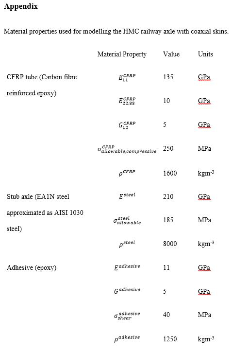
4.1 Material properties
Material properties and performance criterion are established for the three structural components of the composite axle: 1. the carbon fibre reinforced epoxy composite tube; 2. the steel stub axles; and 3. the epoxy adhesive. The Cambridge Engineering Selector (CES EduPack software16, of Granta Design Limited was used to identify materials for the HMC railway axle following the CES approach to material selection illustrated by Ashby and Cebon17. The EA1N grade railway steel is not present in the CES database, therefore, ‘carbon steel, AISI 1030, normalised’ is used as a close approximation by composition. A listing of the material properties is provided in the Appendix.
4.2 CFRP tube modelling conditions
A composite layup was created using Abaqus CAE18 with alignment to the global railway axle coordinates shown in Figure 1. Based on the low torsional loading being applied in comparison to the bending load on the axle, a layup was specified comprising 90% of fibres along the axis of the tube (0°) and the remaining 10% of fibres in the hoop direction (90°). Further layers of ±45° fibres could be added subsequently to align with torsional inputs, to provide protection to the 0° fibres and facilitate a progressive fibre angle variation through the laminate stack.
After conducting a sensitivity study, a global mesh size of 7.5 mm with 36 radial elements was chosen to accurately, and efficiently capture the feature details. A computational run time of approximately 2.5 minutes was achieved which allowed convergence to optimal model parameters within a manageable time frame.
4.3 Parametric study of the structural HMC railway axle assembly
The most relevant parameters to be varied for the HMC railway axle assembly are the CFRP tube outer diameter ( ), CFRP tube thickness ( , steel stub axle extension thickness ( ), and the bond overlap length, ( ), as shown in Figure 5.
For a fixed CFRP outer diameter, the inner diameter ( ), and hence thickness, follows the analytical solution whereby a larger diameter tube requires a smaller thickness to sustain an equivalent maximum stress. This is evident from the equation for bending stress19:

The maximum bending stress, , occurs under the applied bending moment, , a distance, , from the neutral axis for the CFRP tube having a second moment of area, . The CFRP tube is defined by the inner and outer diameters, and , respectively.
Applying the maximum allowable compressive stress of 250 MPa for the CFRP tube, the corresponding inner diameter and thickness are calculated. Using these dimensions along with the density of the CFRP tube material, the mass of the CFRP tube is found to reduce as the outer diameter increases as shown in Figure 6. The mass of the HMC railway axle assembly, however, increases with increasing CFRP tube diameter. This is a result of the mass of the steel stub axle extension (fixed at a length of 200 mm) correspondingly increasing with the CFRP tube diameter. This suggests that to minimise the mass of the HMC railway axle, the entire assembly, including the stub axle mass, requires consideration, rather than simply the mass of the CFRP tube itself.
The outer diameter of the CFRP tube is fixed at 225 mm and the mass of the stub axle is minimised. This is achieved by hollowing the stub axle extension as it increases in volume proportionally with an increase in the CFRP tube diameter. Hollowing the stub axle extension to reduce the thickness of the steel at the overlap leads to an associated increase in stress within the steel. This is indicated in Figure 7, which shows that, as the thickness of the steel increases in the stub axle extension, the stress reduces. However, beyond approximately 30 mm a plateau in the stress value is reached whereby further increases in thickness does not reduce the stress further. Note that, as expected, the stress in the CFRP tube is not affected by changes to the thickness in the overlap of the stub axle. However, stress in the adhesive reduces as the thickness of the steel reduces. This suggests that the wall of the steel stub axle extension is deflecting, relieving an edge binding effect caused by the stub axle locally compressing the adhesive layer.
A decision was taken to fix the thickness of the steel within the bond overlap to 10 mm. At this level, the stress in the steel is below the allowable level of 185 MPa, minimising the mass of the stub axle, hence the overall HMC railway axle assembly mass.
An analysis of the bond overlap is required to fix the parameters associated with the joint itself. Having done this, the overall CFRP tube can be specified. Figure 8 shows the relationship between the overlap length of the bond and the stresses that develop within the components. It is evident that the stress in the steel reduces with an increase in the overlap length up to approximately 100 mm of overlap. The stresses within the CFRP tube and the epoxy adhesive are less sensitive to the overlap length. For this reason, the overlap length of the adhesive bond is fixed at 100 mm.
While the stress within the steel stub axle has been reduced below the design allowable of 185 MPa, the stress within the adhesive remains at 70 MPa which is above the allowable stress of 40 MPa. This peak stress in the adhesive occurs in a small region at the inner end of the overlapping region. To mitigate this, the thickness of the CFRP tube is increased locally from 7 mm to 15 mm, by overwinding hoop (90°) fibres. This reduces the compressive and peel loads significantly by improving the bending stiffness of the CFRP tube in the overlap region. Having stiff adherends in the joint region, however, increases the peak shear stress. Adding short tapers to the outer diameter of the CFRP tube and the inner diameter of the steel stub axle extension provides compliance at the edges of the joint and reduces the peak stress in these positions.
4.4 Finalised parameters of the HMC railway axle
A structural HMC railway axle has been designed to meet the load cases with the Standard EN 13103-1 with the overall objective of reducing the mass. The final dimensions of the structural HMC railway axle assembly are shown in Figure 9. Parameters identified for optimisation of the HMC railway axle assembly were the CFRP tube outer diameter ( ), CFRP composite tube thickness ( ), steel stub axle extension thickness ( ), and the bond overlap length ( ). These parameters have been defined in observation of the allowable stresses. The mass of the optimised axle is 200 kg (50% mass reduction). Further optimisation of the design can be carried out to include:
- A stiffness analysis of the HMC railway axle assembly to minimise deflections at the bearings, strains within the CFRP tube matrix and shaft whirling effects.
- Addition of off axis fibres to address levels of torsional loading and to protect the load bearing axial fibres.
- Specifying short, compliant tapers to the stub axle extension and CFRP tube to reduce peak stresses in the bond.
An approach for the design of a multifunctional composite railway axle utilising coaxial skins has been presented. The basis of the design is a structural HMC railway axle with an outboard bearing arrangement. This assembly comprises a CFRP tube with steel stub axles bonded into either end. An objective of the HMC railway axle is to minimize the mass of the axle while meeting the loading requirements within the Standard EN 13103-1. Compared to a solid steel axle weighing 400 kg, the optimised HMC railway axle has a mass of 200 kg representing a reduction of 50%.
The structural HMC railway axle is surrounded by coaxial skins performing a specific function to meet secondary requirements. These include fire and ballast skins to protect the HMC railway axle core. An outer pigmented layer provides visual identification of the axle class along with protection against environmental agents. Integrated into the railway axle is a SHM layer to provide feedback on the integrity of the composite tube and adhesive bonds during the operating life. An additional, less sophisticated tether is added providing a global indication of the integrity of the HMC railway axle. This tether will have the further benefit of retaining the wheel should the HMC railway axle undergo a catastrophic failure.
HMC: Hybrid metallic-composite; CO2: Carbon dioxide; CFRP: Carbon fibre reinforced polymer; FRP: Fibre reinforced polymer; NDT: Non-destructive testing; UT: Ultrasonic testing; SHM: Structural health monitoring; FST: Fire, smoke and toxicity; UV: Ultraviolet; EMC: Electromagnetic compatibility; CES: Cambridge Engineering Selector; CAE: Computer-Aided Engineering.
Availability of data and materials
Data generated and analysed during this study are included in this published article.
Competing interests
The authors declare that they have no competing interests.
Funding
The first author would like to acknowledge the funding support of the Engineering and Physical Sciences Research Council through the: “EPSRC Future Composites Manufacturing Research Hub [Grant number: EP/P006701/1]” and “EPSRC Industrial Doctorate Centre in Composites Manufacture [Grant number: EP/L015102/1]”.
Authors' contributions
P.J. Mistry and M.S. Johnson conceived the composite railway axle design and drafted the article, C.A. McRobie carried out the finite element analysis of the composite axle design and I.A. Jones reviewed and corrected the article. All the authors read and approved the final manuscript.
Acknowledgements
Not applicable.
- CO2 Emissions From Fuel Combustion Highlights 2018. IEA Statistics. International Energy Agency (IEA) 2018
- J.-P. Loubinoux, L. Lochman, Moving towards sustainable mobility: A strategy for 2030 and beyond for the European railway sector (International Union of Railways (UIC) - Paris, France, 2012)
- J.J. Carruthers, M. Calomfirescu, P. Ghys, J. Prockat. The application of a systematic approach to material selection for the lightweighting of metro vehicles. Proceedings of the Institution of Mechanical Engineers, Part F: Journal of Rail and Rapid Transit 2009; 223: 427–437
- EN 13103-1:2017, Railway applications. Wheelsets and bogies. Part 1: Design method for axles with external journals. CEN. Brussels, Belgium
- 10.1177/0954409719877774P.J. Mistry, M.S. Johnson. Lightweighting of railway axles for the reduction of unsprung mass and track access charges. Proceedings of the Institution of Mechanical Engineers, Part F: Journal of Rail and Rapid Transit 2019. DOI: 10.1177/0954409719877774
- J. Batchelor, Use of fibre reinforced composites in modern railway vehicles. Mater. Des. 2, 172–182 (1981). DOI:10.1016/0261-3069(81)90017-0. Article.
- NEXT generation methods, concepts and solutions for the design of robust and sustainable running GEAR (NEXTGEAR). S2R-OC-IP1-02-2019. Horizon 2020, Shift2Rail
- N.E.X.T.G.E.A.R. Project, D3.1 - Analysis of the state of the art for composite materials suitable for rail wheelsets and related manufacturing processes. 2020
- A. Bracciali, G. Megna. Inside frame bogies & air wheelset a winning marriage. In: 10th International Conference on Railway Bogies and Running Gears Budapest, Hungary, 2016, pp. 12–15
- BS EN 61373:2010. Railway applications. Rolling stock equipment. Shock and vibration tests. BSI. London, England
- C. Worrall, E. Kellar, C. Vacogne. Joining of fibre-reinforced polymer composites: a good practice guide. 2020. Composites UK
- BS EN 50125-1:2014, Railway applications. Environmental conditions for equipment. Part 1: Rolling stock and on-board equipment. BSI. London, England
- BS EN 45545-2:2013 + A1:2015. Railway applications. Fire protection on railway vehicles. Requirements for fire behaviour of materials and components. BSI. London, England
- S. Hind. Predicting and measuring thermal conductivity in carbon-epoxy unidirectional tape and textile reinforced composites. University of Ottawa (Canada), 2010
- S. Cervello, D.L.U.R.S.A.K. Sala: Development of innovative anti impact coating return from experience. Proc 17th International Wheelset Congress. Kiev, Ukraine, 2013
- CES EduPack, version 18.1.1. Copyright Granta Design Limited, 2018
- M.F. Ashby, D. Cebon. Case studies in materials selection. Butterworth Heinemann, 1999
- Abaqus/CAE, 10 Rue Marcel Dassault, CS 40501 78946 Vélizy-Villacoublay Cedex, France: Dassault Systèmes, 2017
- M.F. Ashby, Materials selection in mechanical design, 3rd edn. (Butterworth Heinemann, London, 2005)