3. 1. XRD
The XRD diffraction spectroscopic technique was employed to study the structure of the polymer composite films. The XRD patterns of SWCNTs, TiO2 and MWCNTs/TiO2 nanocomposites are shown in Figure 1. The two broad XRD peaks are visible in the SWCNTs' XRD pattern, at 26.13 and 43.63, which correspond to the graphic carbon planes of (200) and (101), respectively (JCPDS 75-1621)[34,35]. The typical diffraction peaks can be found at 25.46◦, 32.45◦, 36.23◦, 54.09◦, 59.06◦, 62.89◦, and 71.32◦. The as-prepared sample can be classified as anatase TiO2 when compared to the standard pattern (JCPDS no. 21-1272). The peaks mentioned above correspond to the crystal planes of (101), (004), (200), (211), (204), and (220)[36]. In the range studied, no characteristic peaks of CNT can be found in the spectra of the SWCNTs/TiO2 nanocomposite. This is due to the overlap of the intense peaks of the CNT (200) and anatase (101) reflections, as well as the relatively wide mass disparity between CNT and TiO2[37]. The composite material's main diffraction peaks are sharp and display strong crystallinity. In comparison to pure TiO2 nanoparticles, the intensity of XRD peaks of SWCNTs/TiO2 nano-hybrid specimens was decreasing (Fig. 1).This shows that the average size of the crystallite of the nanocomposites is smaller, due to TiO2 NPS adsorption on the SWCNTs surface, which decreased agglomeration and thus crystallite size[38]. The equation of Debye–Scherrer’s D= kλ/(β cosθ) was applied to calculate the average crystallite sizes[39], in which k is a constant =0.9 or 1, β is full width at half the diffraction peak's maximum intensity. The estimated crystallite size of the TiO2 and SWCNTs/TiO2 was 20 nm and 15 nm, respectively.
The relatively broad diffraction peak positioned at 2θ = 21.54◦ was revealed in Figure2 which contained the XRD spectra for pure CMC/PEO, this confirm semi-crystalline nature of CMC/PEO due to interaction between chains of the CMC and PEO by hydrogen bonding[40]. The presence of SWCNTs/TiO2 as nanofiller in the pure CMC/PEO[41] was identified by the existence of the peaks along with increase in intensity with content of SWCNTs/TiO2 and decline in the intensity of the diffraction peaks of characteristic of CMC/PEO. On the basis of the XRD patterns of the prepared samples, Bragg’s law d=nλ/(2 sinθ), where n = 1 is reflection order, θ is angle of Bragg’s, λ = 1.5405 Å was conducted to estimate the d-spacing. The equation of Debye–Scherrer’s was applied to calculate the average crystallite sizes of the samples. Hermans and Weidinger method Xc=Ac /AT×100 is used to analyze the crystallanity (Xc). In this method, Ac is area of amorphous haloes and AT is the total area of peaks (area of crystalline and amorphous peak)[42]. The estimated parameters are shown in Table 1. As shown in the Table, a shift to higher angle and a decline in inter planar separation were referred to the characteristic diffraction peak at 21.54o in nanocomposites (4.8wt.%). It's possible that this is due to the filler molecules being incorporated into the matrix's interplaner spacing [43]. Furthermore the new crystalline peaks (at 2θ =25.46◦, 32.45◦, 36.23◦, 54.09◦) identified in CMC/PEO-SWCNTs/TiO2nano-composite can be compatible with peaks of the pure SWCNTs/TiO2. The figure also revealed that the formation of the complexation between nanoparticles and CMC/PEO composite resulted in a rise in the intensity of the crystalline peaks as the loading of filler particles increased. This result is in perfect harmony with the FTIR analysis.
Table 1: XRD parameters of pure blend and SWCNTs/TiO2 filled polymer blend.
|
A concentration of CNT/TiO2 (wt%) NPs
in CMC/PEO
|
2θ (degree)
|
d-Spacing (Å)
|
Average size of crystallite
(D)
|
Inter-crystallite
separation R (Å)
|
Crystallanity(%)
|
|
0
|
21.62
|
4.10
|
15.32
|
5.135
|
55.32
|
|
0.4
|
21.54
|
4.12
|
17.14
|
5.155
|
48.67
|
|
1.6
|
21.28
|
4.17
|
18.41
|
5.217
|
35.95
|
|
3.2
|
21.32
|
4.16
|
16.87
|
5.207
|
38.49
|
|
4.8
|
21.15
|
4.19
|
19.54
|
5.249
|
33.98
|
3.2. TEM
The increased resolution of TEM examination allows for a better understanding of the specific details of nanostructures. Figure3(a,b) illustrates TEM images of TiO2 NPs synthesized by sol-gel and the CNT–TiO2 nanocomposites fabricated by a simple mixing technique. TEM images of TiO2 NPs (Fig. 3a) revealed that during the production stage, most of the particles were spherical and clustered to form bigger aggregates, and nanoparticles size were almost (30-22) nm, somewhat larger than the size determined from XRD analysis [20 nm][44]. The presence of well-spread TiO2 NPs with an essentially narrow size distribution throughout the tube walls of the CNT–TiO2 sample can be seen in TEM images of the sample (see Fig. 3b). Also, the figure 2b shows that TiO2 NPs are well ornamented on the surface of CNTs, resulting in CNT–TiO2 nanocomposites. This suggests that TiO2 NPs may bind to the surface of CNTs via van der Waals interactions[45].
3.3. FTIR Spectroscopy Analysis
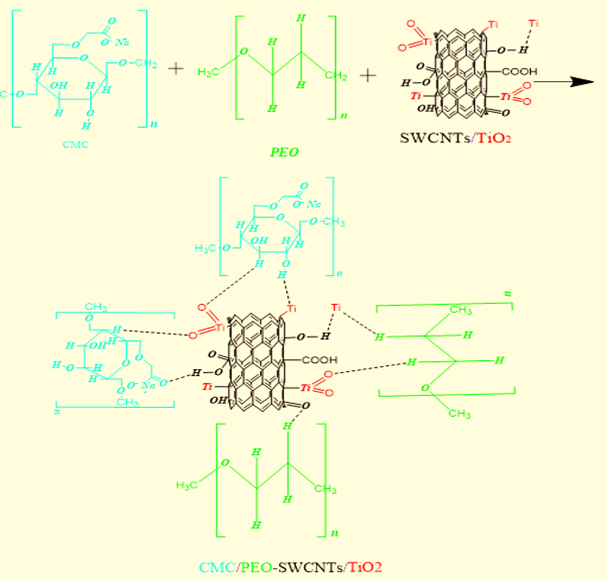
Using FTIR spectroscopy helped to realize the chemical composition and the possible interactions between CMC/PEO and SWCNTs/TiO2 nanocomposites. The results of analysis also revealed that specific intramolecular and intermolecular interactions of polymer chains caused the complexation to occur between two polymers, and that hydrogen bonding caused the complexation between the CMC/PEO and SWCNTs/TiO2. The interaction between all the materials was identified by using the IR absorption bands in spite of their observed changes in the position, shape and intensity. All samples recorded by FTIR spectra in the wavenumber range from 500 to 4000 cm-1 were shown in Figure 4a. The selection of the highlighted region was regarded to the most interaction existed between the blend and the dopant. At 1059 cm-1, which attributed by C–O- stretching of pure CMC, the vibrational bands are noticed[46]. Up to the level of CMC/PEO/ (4.8 wt.%) SWCNTs/TiO2, the decrement of intensity and increment of the broadness was observed. The analysis also revealed that a slight shift from higher to lower wavenumber of 1059 to 1045 cm-1 appeared. The occurrence of such slightly shift was regarded to the existence of oxygen from C–O- interacted with OH or COOH groups from SWCNTs presence in the SWCNTs/TiO2. In the other side, Mazuki et al suggested that the band at 1323cm-1 is assigned to -OH bending[47]. The peaks observed between 2908 and 2845 cm-1 were similar and dissimilar C–H2 bond’s osculation. In Fig. 2a, the band at 3331 cm-1 relates to O–H stretching is noticed. The hydroxyl band intensity was decreased upon the addition of the Nano-filler. This reflection might refer to the complexation of SWCNTs/TiO2 with blend. As noted in Figure 4b, the intensity of the peak at this band reduced upon the adding of SWCNTs/TiO2 NPs and changed into the high wavenumber (1330 cm-1). At 1589 cm-1 wavenumber a remarkable band existed, which relates to C=O of COO-. Such a results belongs to CMC/PEO blend[48]. In regards, when the content of the Nano-filler is added to the polymer blend, the peaks begin to decrease. Mejenom et al.[49]stated that due to the creation of intermolecular hydrogen bonding between the C=O of the CMC/PEO with the SWCNTs/TiO2 surface, the peak shifting might occur. The interaction between OH+ and Ti+ in the SWCNTs/TiO2 can explain this shifting, with ether group in the polymer blend where the lone pair electron of oxygen will attract the Ti molecule to stick to it and then contribute towards the protonation process as shown in scheme1[50].
3. 4. DSC studies
DSC is used to study the thermal response of SWCNTs/TiO2 doped CMC/PEO polymer nanocomposites and the thermograms of the existing nanocomposites films are displayed in Figure 5. The DSC curves of nanocomposites films mainly give the sample three characteristic temperatures, i.e. the temperature of the transition of the glass(Tg), the temperature of melting, and the temperature of degradation. The transformation takes place in the polymer matrix as the temperatures is increased by the temperature of the glass transition and includes the onset of motion and bond rotation of the thermally induced chain segment. The transition of glass is therefore an essential parameter for predicting the polymer's thermal properties[51]. As the midpoint of the region of rising heat flow in all films, the glass transition temperature is measured. Pure CMC/PEO blend has glass transition at 58.67 ° C and by promoting chain mobility; it reduces slightly with the adding of nanofiller, so that ionic conductivity increases with ion motion[52,53]. The CMC/PEO/(4.8 wt.%) SWCNTs/TiO2 film shows the low Tg, which induces the higher segmental motion of polymer chain. The ions can easily pass across the polymer matrice in this system, i.e., there is high ionic mobility. This will help boost the transport of ions and the complex system of CMC/PEO/(4.8 wt.%) SWCNTs/TiO2 NPs displays elevated electrical conductivity. In addition, the observed change in Tg values of the prepared films in DSC thermograms suggests that the blend-SWCNTs/TiO2 NPs interaction confirms the complexation [54]. The presence of one glass transition temperature in the CMC/PEO blend confirms the miscibility between CMC and PEO[55]. As the doping of SWCNTs/TiO2 (251.79-267.56 °C) increases, the melting temperature of the polymer nanocomposite rises due to the obstruction of the polymer chain's mobility and rotation. The melting point is boosted by the rise in the energy barrier. At higher temperatures, the thermal stability of polymer blending increases with doping content. The increase in driving force makes the degradation temperature to rise from 307 to 293 ° C due to the interaction of SWCNTs/TiO2 with the CMC/PEO blend[31].
3. 5. Thermogravimetric (TGA)
Thermal stability of PSEs is an important parameter in the manufacture of electrochemical devices that are supported and endurable. A particular technique that can be used to examine the thermal stability of prepared films is thermogravimetric analysis (TGA). Weight loss after heating the samples over the temperature range of 15 to 700 oC can be used to reflect the thermal stability of the films. TGA thermograms of pure blend and various contents of doped CMC/PEO films of MWCNTs/TiO2 NPs are shown in Figure 6. Three different stages of deterioration are revealed by examination of TGA curves. The first stage was observed at 35-130 oC, and the water was completely evaporated or dehydrated in this area, according to Ahmad et al. [56]. In polymer systems, the moisture content determines the percentage of initial weight loss. Liu et al.[57] reported a similar finding, where the first stage corresponds to the decrease of film moisture through the process of dehydration and evaporation that leads to the initial loss of weight. The second stage of weight loss can be due to the method of decomposition of polymer systems and the maximum decomposition temperature has reached 355 oC. In the CMC-PEO backbone, the CO2 from the carboxylate groups (COO-) has decomposed and thus contributes to a sudden decrease in weight loss[58] Meanwhile, at a temperature range of 280-355 oC, the decomposition of bond scission in the backbone of the blend is thought to have occurred[59]. This reveals that the temperature of decomposition for the entire samples is beginning to rise with the addition of nanofiller in the current system. This could be due to the entire content creation of homogeneous polymer electrolytes, allowing CMC-PEO to obtain any charge of ionic[60]. Based on this process, it is clear that when MWCNTs/TiO2 NPs are introduced into the system, CMC-PEO would provide more ion hopping sites and thus lead to an increase in temperature of decomposition. Su et al.[61] stated that the Millard reaction and crosslinking between the two polymers and nanomaterials lead to the improvement of thermal stability by generating more free volume space when two different polymers have been blended with nanomaterials.
3. 6. UV-Vis. analysis
The UV–Vis spectra of CMC/PEO blend and Nano-composites films were shown in Figure 7. Owing to the presence of C=C and/or C=O mainly in the tail–head of the blend film, the absorption band at 198 nm in polymer blend was ascribed to n-p* transitions and around 215 nm was attributed to p - p*. It can be noted that various SWCNTs/TiO2 were treated by blend. Note that blend doped various SWCNTs/TiO2 nanoparticles contents the absorption bands and band edges of the SWCNTs/TiO2 doped polymer blend have shifted towards higher wavelengths, with varying absorption intensities[62].These band shifts confirm the formation of inter/intramolecular hydrogen bonds, primarily between SWCNTs/TiO2 ions and adjacent functional groups of the polymer blend that are consistent with FTIR results. The change in the energy band-gap in the doped polymer blend reflects the difference in crystallinity within the polymeric matrices which results in a shift in the absorption edge that are consistent with XRD results[53].
3. 6. 1. Measurement of optical energy band gap
The relationship between the absorption coefficient (a) and Eg, is well known to obey the classical Tauc's expression. The optical energy band gap is calculated using the observed UV–Vis spectra by translating the spectra into Tauc's plots. We use Mott and Devis' frequency-dependent a to convert the absorption spectrum into Tauc's plot[53].
α(ν)= β(hν-Eg)n / hν (1)
where n is an empirical index equal to 0.5 or 2 for direct or indirect allowed transition in the quantum mechanical sense and β is a constant. Figure 8(a, b) shows the calculated Eg for all of the samples as well as their variations. The bandgap reduces as dopant concentration rises, as shown in Figure 5(a, b). The presence and change of the optical energy gap Eg can be explained by assuming that cross-linking occurs within the amorphous phase of the polymer blend, reducing the ordering degree in these parts[39]. As observed in FTIR studies, the ions in SWCNTs/TiO2 interact with functional groups of polymer blend and create a complex through intramolecular and intermolecular hydrogen bonding.
3. 7. AC conductivity
The AC impedance analysis can be used to understand the electro-activity of polymeric materials. The AC conductivity of the CMC/PEO blend and MWCNTs/TiO2 doped CMC/PEO nanocomposites is shown in Figure 9a at different frequencies varying from 100 to 106 Hz. It can be observed that, because the trap charges in the polymer matrices are not in equilibrium, the AC conductivity is observed to be weakly frequency (f) dependent at the low frequency region and the ions can reside relatively for a long time, and thus there is more accumulation of charge at the electrode/electrolyte interface, which delays ion mobility and consequent decrease in conductivity[39]. The conductivity revealed an exponential increase in the high frequency region with f of electrical field applied suggesting charge carrier hopping[50]. The embedded blend of SWCNTs/TiO2 has the highest conductivity than that of the pure blend. In the CMC/PEO blend, the uniform distribution of nanofiller increases the normal orientation of the nanocomposites, leading to higher AC conductivity. Up to 3.2 wt.% of SWCNTs/TiO2 loading is observed of the optimum conductivity of the nanocomposite and after that the conductivity is observed to be reduced, these findings comply with previous study[63]. This means that the grain boundaries are enhances by the interfacial interaction between SWCNTs/TiO2 and the CMC/PEO blend, and this is higher at 3.2 wt.% dopant. The uneven distribution of SWCNTs/TiO2 in the polymer matrices contributes to the creation of aggregates or clusters in the nanocomposite, which restricts the mobility of charge carriers through the polymer matrice and thus reduces the ac conductivity at a higher nanofiller loading (4.8 wt.% of SWCNTs/TiO2)[64]. The improvement in ionic conductivity with the increasing content of SWCNTs/TiO2 nanoparticles may be due to the interaction of the nanoparticles with both the anion and cation. The ion-pairing is obstructed by this and the free charge carriers are increased. The SWCNTs/TiO2 nanoparticles filler enhances the ionic conductivity of nanocomposite by impeding the reorganization of the crystalline phase of CMC/PEO chains, according to the Lewis acid-base model[65]. Compared to that of the pure blend, the size of the filler is very small; the filler is able to penetrate into the polymer matrice and facilitate interaction between ions, plasticizer, and molecules of the polymeric matrix chains. The cohesive force between the chains of polymer is thus decreased and gives a more flexible segmental chain movement as well as MWCNTs/TiO2ions conducting pathway at the filler surface[66]. The ionic conductivity mechanism of MWCNTs/TiO2 (3.2wt.%) doped CMC/PEO nanocomposites was investigated at temperatures ranging from 300 to 398 K as shown in figure 9b. As the temperature increases, it is obvious that the charge carriers are activated thermally, and the free volume increases. Therefore, via the coordinated ether oxygen sites, more vacant sites are produced for the ions hopping , which in turn increases conductivity[67]. As shown in Figure 10, the s-value for SWCNTs/TiO2 (3.2wt. %) doped CMC/PEO nanocomposites, examined from the slope of the linear parts of the plots in Figure 8b, and was plotted with temperature. As can be pointed out, 0 < s < 1. The value of s reduces with rising temperature for the SWCNTs/TiO2 (3.2wt. %) doped CMC/PEO. It reduces at first, however, for the nanocomposite sample, and then increases with temperature. The correlated barrier hopping (CBH)[68] and the large Polaron tunneling (LPT) models are the best-suited mechanism for electrical conduction in the sample on the basis of these results[69]. The charge carrier hops between the sites over the potential barrier dividing them in the CBH model.
3. 8. Dielectric constant
Using dielectric analysis, the ion dynamics in the polymeric matrices were investigated. The variance of dielectric permittivity in the real ε' and imaginary ε" of prepared samples at RT is presented in Figure 11(a, b). The ε' in the material depends on the existence of the ions and disorder[70]. The charges polarization at near of the electrodes will lead to high of the ε' at low frequencies. This polarization of electrode is followed the non-Debye nature of the SPEs[68]. At low frequency region, the jump of ions along the applied field in the energy barrier make the dielectric constant is high. There is no hopping of charge carriers in the high-frequency region and oscillation is only accomplished without reaching the surface of electrode. The ε' is therefore constant for all films in the high-frequency region[6]. The dielectric constant value increases up to 3.2 wt.% of SWCNTs/TiO2 concentration and then decrease.
As shown in Figure12, the Cole-Cole diagram (Argand plots) of the prepared films is plotted to describe the essence of the relaxation mechanism at room temperature. It is obvious that the patterns are distinguished by two semicircles for all films whose centers do not end on the actual part of the axis of the electric modulus (M'). This behavior suggests that the relaxation mechanisms of the studied samples are of the nonDebye model[71]. The semi-circuit radius of the SWCNTs/TiO2 (3.2 wt.%)/CMC/PEO sample is obviously small compared to CMC/PEO blend and the other samples that confirm the improvement of ionic conductivity[72].