The workflow model to in-built proposed PMU in Industrial IOT scenario is illustrated in cumulative description in Fig.2. The section of perception layer deals with data analysis and faces lot of challenges. For example, if we consider the industrial data of power consumption in a plant or industry with respect to the product portfolio [24,25] following points are requisite:
- Precise volume data of energy consumption.
- An accurate and precise record of historical production data.
The information of the above two data sources is reconciled before applying any machine learning algorithm as a business intelligence tool. The energy measurement units comprising sensors are needed to be installed to acquire this collective data chain for the first point. This will help in building the Power Task Clustering (PTC) algorithm. The second point faces myriad challenges as real-time data analysis is required. The manual data entry is added with inaccuracies and starts and end time estimation needs proper framing to figure out sleep and awake intervals. In this work following perturbation viz. random fluctuation in sensor data, reduced sensor data frequency and imprecise manufacturing execution system are not considered.
The acquired industrial data can now be analysed by using business intelligence via PTC algorithm to check on power consumption and sleep/awake time interval can figure out. These figured data intervals are the critical requirement for the designed PMU in this architecture. The PTC algorithm (flowchart for same illustrated in Fig. 2(b)) employed to schedule task for PMU is enlisted below:
- Initially, all data are marked unexamined, and each task forms a separate cluster.
- Sort all task in a decreasing order according to their duration time.
- Repeatedly merges task by zeroing the data with high duration time if total power consumption is not increased.
- Mark the data examined.
- When two clusters are merged, the task is ordered accordingly to their latency and throughput.
- Until all data are marked examined.
To figure out sleep and awake time intervals task scheduling is discussed in next section.
2.1 Task Scheduling
The IIOT perception layer data request is modelled as a task in which the time is partitioned into discrete time slots, where si is start time, ei is end time. wi is a time slot for workload (ei - si). time require by a task can be define by function of (si, ei, wi). Without loss of generality, we assume that min si = 0 and max ei = T. for each task in time duration of (Tsi, Tei] power is allocated as Pai, I = 1, 2,…,n. which is the power required in awake mode and Psi power required in sleep mode.
Parameters considered for task scheduling are:
Tsi - start time
Tei – end time
Tfi – time duration (ei - si)
Pa - power in awake mode (for Tfi time, i.e., Paei – Pasi)
Ps - power in sleep mode (for Tfi time, i.e., Psei – Pssi)
I - power for idle scheduling (i.e., power required in checking for the arrival of a new task) function for si, ei, and fi.
- In sleep mode task is not performed, but static, dynamic and clock switching power Ps (si, ei, fi) is require in gateway layer.
- At time Tasi a task is executed in awake mode, in perception layer and power is consumed till Taei (awake end time), so power consumed in awake in mode is Pai (i=1,2, 3..).
- After the task was finished, checking/sensing is performed for the execution of another, and it assumed that power requires for sensing is I (si, ei, fi).
For a given scheduled time duration for T(si, ei, fi) power is summation of Ps for sleep mode; Pai, (i=1,2,3…) for awake mode and I for idle schedule, as idle schedule is for short time (Tfi ≈ 0) it can be neglected.
The total power requirement (eq.1) for task scheduling is ∑𝑛𝑖=1 Pai + ∑𝑛𝑖=1 Ps as illustrated in Fig. 3 however Pai >> Ps.
P(T) = ∑𝑛𝑖=1 Pai (eq.1)
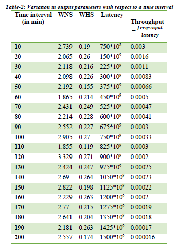
The primary intent of the prediction model for task scheduling is to optimize power by making actuation system work in two modes: sleep and awake. In the sleep mode nodes of actuation system are not working, they can be switched on to awake mode as and when required. The prediction model of sleep interval is considered and analysed for latency and throughput calculation for further optimization. The idle time for awake mode can be set as per the requirement, and the actuation system is transferred to sleep mode in case no work done during this time period. The objective is to switch some nodes to sleep mode when they are not in a working state and wake them up when required. However, the sleep interval of the nodes is impacted by the arrival of the new task.
The next section works on PMU (a subset of control layer) to align the task scheduling in terms of sleep and awake mode.
2.2 PMU Hardware Specifications
The hardware architecture of the proposed PMU constitutes various building blocks, as illustrated in Fig. 4 and are described below:
- Actuation system to monitor and control the AC power units, an integrated switches/relays and optocouplers are interfaced with the microcontroller in context to the required application [20]. A solid-state relay used to turn on/off a device is controlled by a microcontroller.
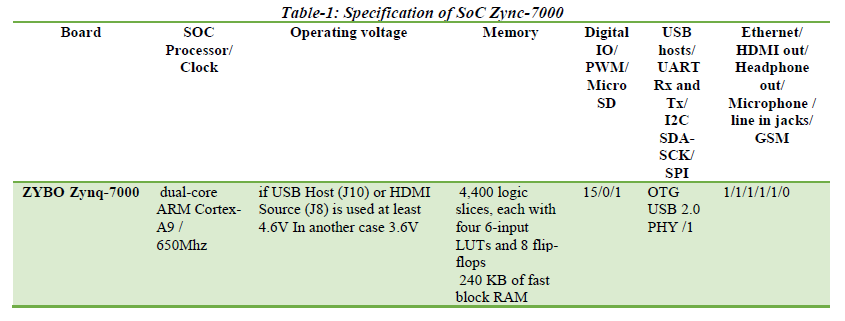
- High-end Microcontroller-is deployed for analysis and processing on data. A Zynq -7000 (AP SoC/FPGA) is used in the high end as an edge device data acquisition module to perform an experimental analysis of the proposed design. The specifications of the SoC are displayed in Table 1
- Servers: are high-end PCs that can be further be exploited on Cloud for wide-scale comprehensibility. The installed servers are MQTT Broker, a Web Server, Analytics Engine server, and highly scalable Storage Server.
- User Application-Working as client-side applications, the user applications can be classified into the following two categories according to the authentication mechanisms.
Client Applications: To use virtual objects hosted as applications in the virtual environment, the client uses the application interface to send requests to the server. Direct access is not allowed within this authentication.
Admin Applications: Unlike the client application, an admin application has the right to access the server directly. Then the admin can promptly make necessary modifications to the system and monitor the performance of the whole system.